background image

Model Number:


Electrical

Requirements:

Item Number:

Quantity:

Manufacturer:

PROJECT INFORMATION

InSinkErator

volts                             phase

Project:

Address:

City/State/Zip:

Contact:

Phone:

Dealer:

City/State/Zip:

Contact:

Phone:

Installer:

Contact:

Phone:

Consultant:

Contact:

Phone:

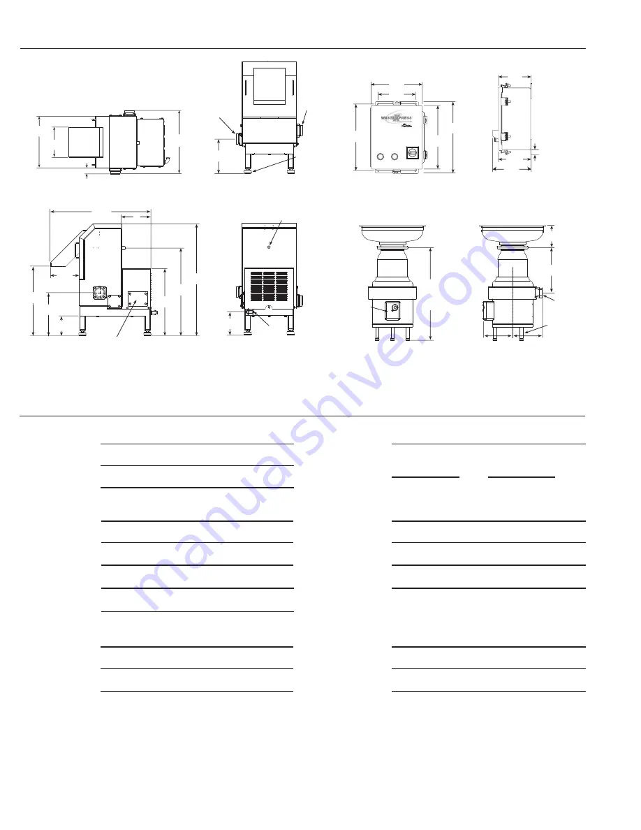
21-3/4"

(552.5 mm)

21-1/8"

(536.6 mm)

26-7/8"

(682.6 mm)

33-1/2"

(850.9 mm)

8"

(203.2 mm)

27-3/8"

(695.3 mm)

7-7/8"

(200.0 mm)

Electrical Connection Cover

14-1/2"

(368.3 mm)

8-1/8"

(206.4 mm)

15"

(381 mm)

18-3/4"

(476.3 mm)

1-5/8"

(41.3 mm)

Waste Xpress Top View

15-1/8"

(384.2 mm)

14"

(355.6 mm)

15-3/4"

(400.1 mm)

9-7/8"

(250.8 mm)

8-1/4"

(209.6 mm)

Control Center Front View

Waste Xpress Side View

9-1/8"

(231.8 mm)

1/2"

(12.7 mm)

Electrical Inlet

1/2"

(12.7 mm)

Hot Water Inlet

Waste Xpress Back View

12-1/8"

(308.0 mm)

2"

(50.8 mm)

NPT Outlet

(Either Side)

2"

(50.8 mm)

NPT Inlet

(Either Side)

Leveling Foot 

Adjustment Range

2-3/4"

(69.9 mm)

Waste Xpress Front View

8-5/8"

(219.1 mm)

Disposer Front View

External Electrical 

Connection Cover

2"

(50.8 mm)

NPT Outlet

Adjustable Legs

Disposer Side View

8-3/4"

(222.3 mm)

8-3/4"

(222.3 mm)

13"

(330.2 mm)

23-3/4"

TO

31-1/8"

(603.3 mm

TO

790.6 mm)

6-1/2"

(165.1 mm)

Control Center Side View

5-1/4"

(133.4 mm)

5-5/16"

(134.9 mm)

6-3/4"

(171.5 mm)

1" 

(25.4 mm)

DIMENSIONS

Summary of Contents for Model WX-300

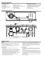
Page 1: ...gh application contact factory Reel Rinse Spray Unit Fisher 2980 Pre Rinse Spray with wall bracket Fisher 2010 WB Pre Rinse Spray with wall bracket Ultra Spray 1 6 GPM 6 1 LPM Fisher 2010 1WB Trough Nozzle 1 25 4 mm NPT WXP Inlet Outlet Flange 2 50 8 mm NPT secondary Trough or high water flow applications Dejamming Wrench ACCESSORIES DISPOSER MOUNTING ASSEMBLIES InSinkErator 2008 Printed in USA Fo...

Page 2: ...ual and in accordance to local state and or national electric codes Position the control panel so that the front surface is recessed 1 1 2 38 1 mm from the front edge of the table and that a minimum clearance of 2 50 8 mm exists between the underside of the table and the top of the control panel for ease of installation and serviceability Position the WX 101A control panel so that it is within sit...

Page 3: ... 6 4 mm drop per foot of run or as local codes apply Floor sink or drains should be installed per local codes but kept clear of yet accessible to pulper Trough applications in excess of 10 3 1 m and or systems plumbed with a cold water supply greater than 7 GPM 26 5 LPM must incorporate the second drain outlet from the pulper and be drained independently to floor sink or drain TROUGH APPLICATION N...

Page 4: ... 8 384 2 mm 14 355 6 mm 15 3 4 400 1 mm 9 7 8 250 8 mm 8 1 4 209 6 mm Control Center Front View Waste Xpress Side View 9 1 8 231 8 mm 1 2 12 7 mm Electrical Inlet 1 2 12 7 mm Hot Water Inlet Waste Xpress Back View 12 1 8 308 0 mm 2 50 8 mm NPT Outlet Either Side 2 50 8 mm NPT Inlet Either Side Leveling Foot Adjustment Range 2 3 4 69 9 mm Waste Xpress Front View 8 5 8 219 1 mm Disposer Front View E...

Reviews:

Related manuals for Model WX-300