6
Installation Instructions
ASSEMBLY
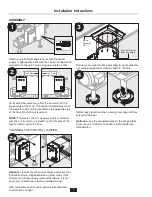
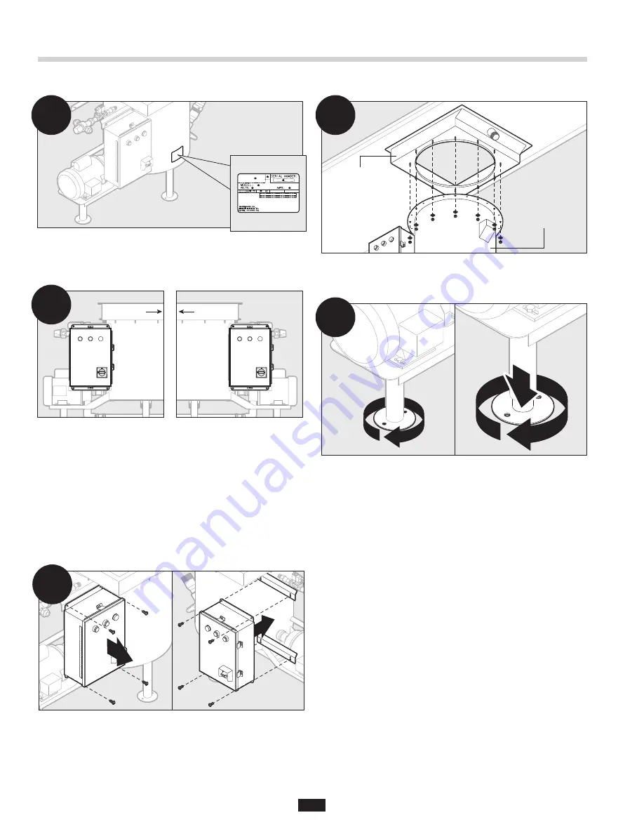
Remove unit from package. Ensure that the power
supply is appropriate based on the control configuration
ordered with the unit. Verify using spec plate on tank.
Verify dish flow and ensure that the control is on the
proper side of the tank. The control should always face
the operator and can be mounted on the opposite side
of the tank if dish flow is reversed.
NOTE:
The waste collector base assembly is shipped
with the control factory-installed on the left side of the
tank for left-to-right dish flow.
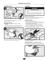
CHANGING THE CONTROL LOCATION
Optional –
to relocate the control, remove and save four
(4) bolts and nuts. Reposition box on other side of tank
and secure with previously removed hardware. It is not
necessary to
disconnect factory-installed wiring.
After relocating control, verify conduit and solenoid
connections are tight.
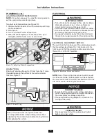
Secure waste collector base assembly to waste collector
tray using provided lock washers and 1/4"-20 nuts.
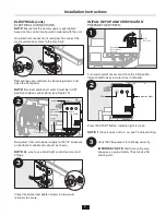
Rotate legs clockwise when viewing from top until they
extend to the floor.
Optional
–
use the provided holes on the flanged foot
to secure unit to floor with anchors (not provided by
InSinkErator).
1
4
2a
Dish Flow
Dish Flow
2
Waste
Collector
Tray
Waste Collector
Base Assembly
3


