7
Installation Instructions
ASSEMBLY (cont.)
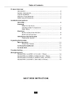
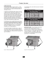
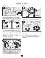
Connect plume hose to collector tank. Turn brass
coupling clockwise to secure.
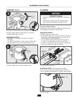
IMPORTANT NOTES:
•
DO NOT
cross thread brass fitting onto plastic
plumbing.
• For ease of installation, connect plume hose first to
waste collector tank then to waste collector tray.
Connect plume hose to waste collector tray.
PLUMBING
WATER CONNECTIONS
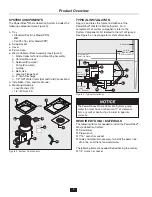
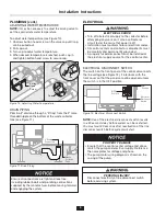
Plumb a hot and a cold water supply line to mixer valve
(see Figure 8). Connections are 1/2" NPT.
IMPORTANT NOTES:
•
Mixing valve can be relocated.
• Hot and cold water lines must match the markings on
mixer valve. If lines are reversed, mixer valve will not
operate properly after adjustment.
• It is recommended that ball type shutoff valves be
installed in line with the cold and hot water lines.
•
A minimum of 30 psi at the mixer valve is needed for
the waste collector to operate correctly.
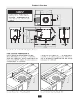
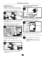
IMPORTANT NOTE:
This air gap meets ASME
A112.1.2-2012 standard and eliminates the need for a
vacuum breaker installed with the system (see Figure 9).
Waste
Collector
Tray
Plume
Hose
6
Waste
Collector
Tank
Plume
Hose
5
PROPERTY DAMAGE
• Installation must comply with all local plumbing
codes.
• If water pressure exceeds the recommended
80 psi, pressure regulators should be used.
Mixer
Valve
Cold Water
Supply Line
Hot
Water
Supply
Line
Figure 8. Water Connections
Air Gap
Figure 9. Air Gap


