background image

Page 4

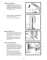
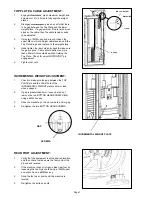
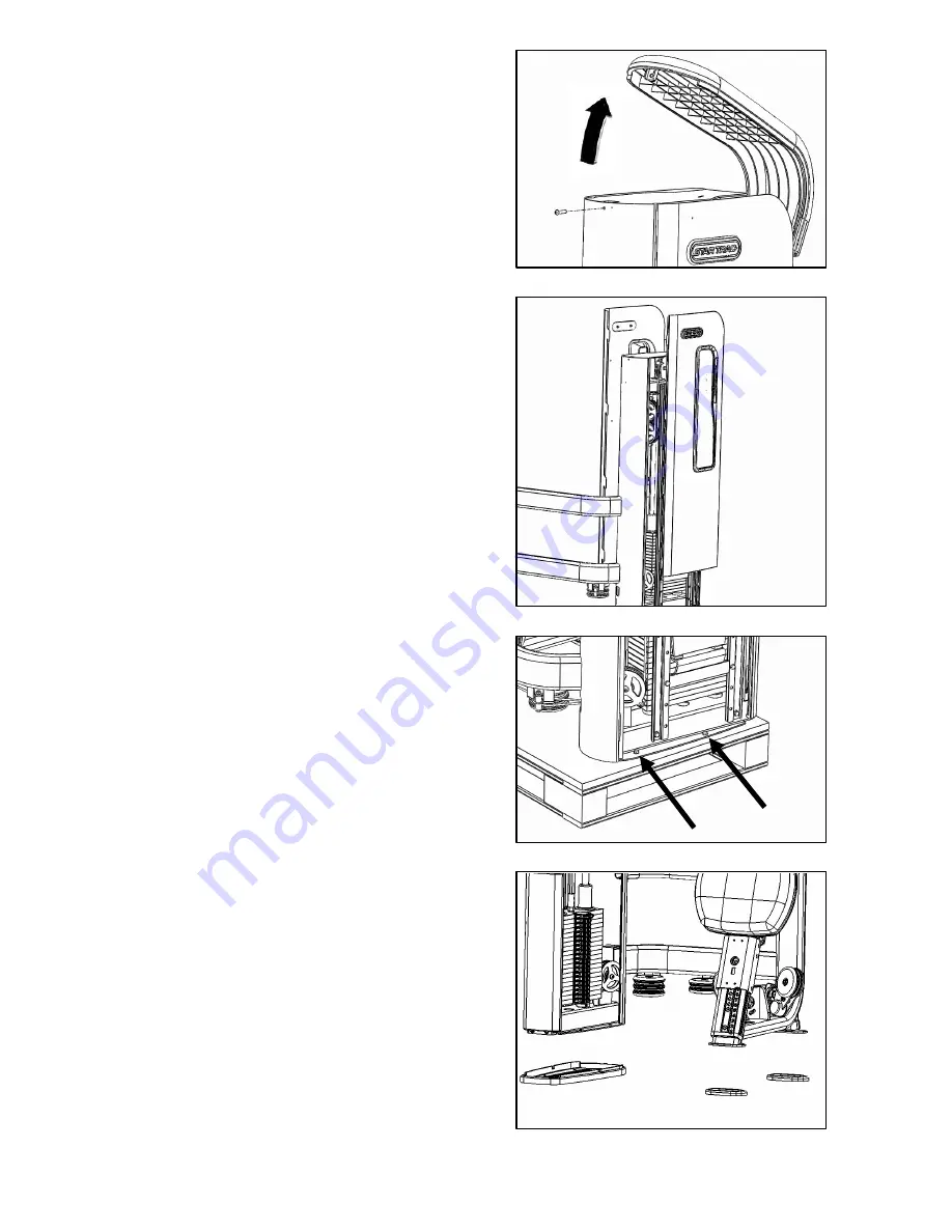
2.

Gripping the top edges of the outside SHROUD lift 
and remove it from the weight stack. Carefully 
store the SHROUD for later use. 

3.

Now repeat step 2 with the inside SHROUD.

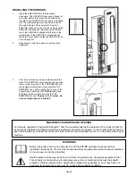
REMOVE THE SHROUDS:

1.

Using a 4MM hex key socket remove the 
(M6,30MM,Button Head Bolt) from the rear of the 
weight stack. Save this bolt as you will need it to 
re-install later. After the bolt has been removed 
rotate the black TOP BUMPER towards the front 
of the weight stack and lift it off. Carefully store the 
TOP BUMPER for later use.

REMOVE FROM PALLET:

1.

After removing the shrouds, listed above, remove 
the bolts securing the equipment to the pallet. The 
bolts can be found inside the weight stack as 
shown. There will also be a bolt through each of 
the small feet.

2.

Once all bolts fastening the equipment to the 
pallet have been removed, carefully slide the 
equipment off of the pallet and place it in the 
desired location.

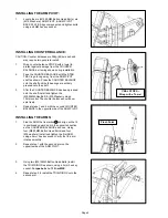
INSTALL PROTECTIVE FEET:

1.

Your equipment shipped with a set of 
PROTECTIVE FEET. Remove the liner from the 
double sided tape located on the inside edges of 
the small PROTECTIVE FEET. Tilt the equipment 
towards the weight stack until the two smaller feet 
lift off the ground, press the PROTECTIVE FEET 
into place and set the equipment back on the 
ground. 

2.

Remove the liner from the double sided tape 
located on the inside edges of the large 
PROTECTIVE FOOT. Now tilt the equipment onto 
the two small feet lifting the weight stack off the 
ground, press the large PROTECTIVE FOOT into 
place and set the equipment back on the ground.

Summary of Contents for IP-S4305

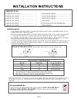
Page 1: ...SHOULDER PRESS IP S4305 INSTALLATION INSTRUCTIONS...

Page 2: ...first obtaining written permission from Star Trac Every effort has been made to keep this information current however periodically changes are made to the information herein and these changes will be...

Page 3: ...738 lbs when fully assembled and occupies an area 148 cm wide by 149 cm deep Star Trac recommends the addition of 1 2 people during assembly and when moving the equipment to its designated point of u...

Page 4: ...weight stack as shown There will also be a bolt through each of the small feet 2 Once all bolts fastening the equipment to the pallet have been removed carefully slide the equipment off of the pallet...

Page 5: ...s been pressed onto the shaft install and tighten the M8 25MM Hex Bolt M8 Washer using a 13mm socket The counter balance should now spin freely 4 Repeat steps 1 and 2 with the second COUNTER BALANCE i...

Page 6: ...Socket Head Bolts and four M8 Washers Tighten using a 6MM hex key Operate the seat up and down by squeezing the red handle the ADJUSTABLE SEAT should operate smoothly GUIDE ROD LUBRICATION 1 Use a ge...

Page 7: ...by loosening the two Nyloc nuts using a 13MM open end wrench and a 6MM hex key 3 Slide the foot up or down until the machine is leveled 4 Re tighten the bolts and nuts TOP PLATE CABLE ADJUSTMENT 1 En...

Page 8: ...not aligned use the palm of your hand and tap the SHROUD down until it is aligned 2 Repeat step 1 with the inside shroud and verify alignment Before using this product it is essential to read the ENT...

Page 9: ...Page 9...

Page 10: ...Part No 620 7934 Rev B 21 Aug 09 STAR TRAC 14410 Myford Road Irvine California 92606 Telephone 800 228 6635 714 669 1660 Fax 714 508 3303 www startrac com...

Reviews: