PAGE 10
STEP 2
Upright BeamS AND REAR CONNECTING FRAME INSTALLATION
Refer to the illustration above for location and orientation of components.
•
Fasten with Bolt (28), at the bottom, Bolt (29) above, Washer (37), and Lock-Nut (35).
Connect Upright Beam (5) to the Bottom Support Frame Assembly. Left side and Right
side. (Refer to the illustration above for placement).
•
Fasten with Bolt (29), Washer (36), and Lock-Nut (35). Connect the Rear Cross Bar(3) to
the Upright Beams (5) and fasten in place.
Summary of Contents for FPC1
Page 1: ...PAGE 1 FPC1 FULL POWER CAGE ...
Page 4: ...PAGE 4 ...
Page 5: ...PAGE 5 EXPLODED VIEW ...
Page 7: ...PAGE 7 COMPONENTS LIST 13 X 4 4 X 1 2 X 2 40 X 2 12 X 2 15 X 4 5 X 4 3 X 1 1 X 2 ...
Page 8: ...PAGE 8 HARDWARE PACK ...
Page 17: ...PAGE 17 ...
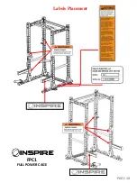
Page 18: ...PAGE 18 Labels Placement FPC1 FULL POWER CAGE ...
Page 19: ...PAGE 19 ...


