background image

PAGE  7

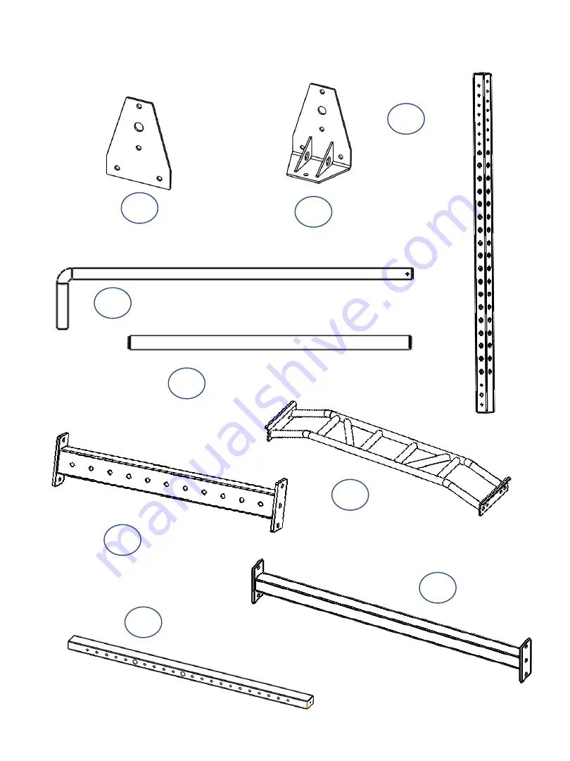
COMPONENTS LIST

13     X 4

4

X 1

2

X 2

40 X 2

12     X 2

15     X 4

5

X 4

3

X 1

1     X 2

Summary of Contents for FPC1

Page 1: ...PAGE 1 FPC1 FULL POWER CAGE ...

Page 2: ...re using the machine As a manufacturer we are committed to providing you complete customer satisfaction If you have any questions or find there are missing or damaged parts please call our TOLL FREE customer service number Our Customer Service Agents will provide immediate assistance to you Table of Contents BEFORE YOU BEGIN 1 IMPORTANT SAFETY NOTICE 3 PARTS LIST 4 EXPLODED VIEW 6 ASSEMBLY INSTRUC...

Page 3: ... wear appropriate workout clothing when exercising DO NOT wear robes or other clothing that could become caught in the machine Running or aerobic shoes are also required when using the machine 8 Use the machine only for its intended use as described in this manual DO NOT use attachments not recommended by the manufacturer 9 Do not place any sharp objects around the machine 10 Disabled persons shou...

Page 4: ...PAGE 4 ...

Page 5: ...PAGE 5 EXPLODED VIEW ...

Page 6: ...PAGE 6 COMPONENTS LIST 7 X 1 6 X 1 18 X 1 9 X 1 8 X 1 10 X 1 11 X 1 16 X 4 23 X 2 17 X 10 14 X 1 ...

Page 7: ...PAGE 7 COMPONENTS LIST 13 X 4 4 X 1 2 X 2 40 X 2 12 X 2 15 X 4 5 X 4 3 X 1 1 X 2 ...

Page 8: ...PAGE 8 HARDWARE PACK ...

Page 9: ...me 1 Bottom Inner Plate 13 and the Bottom Cross Brace 14 place these items towards the one end of the Bottom Base Frame Repeat Step for the Opposite side Fasten with Bolt 29 Washer 36 and Locknut 35 Connect Bottom Foot Plate 15 to Bottom Base Frame 1 and Bottom Inner Plate 13 and the Bottom Cross Brace 14 place these items towards the one end front of the Bottom Base Frame Repeat Step for the Oppo...

Page 10: ...components Fasten with Bolt 28 at the bottom Bolt 29 above Washer 37 and Lock Nut 35 Connect Upright Beam 5 to the Bottom Support Frame Assembly Left side and Right side Refer to the illustration above for placement Fasten with Bolt 29 Washer 36 and Lock Nut 35 Connect the Rear Cross Bar 3 to the Upright Beams 5 and fasten in place ...

Page 11: ...fer to the illustration above for location and orientation of components Fasten with Bolt 29 at the bottom Washer 36 and Lock Nut 35 Connect Upright Beam 5 to the Bottom Support Frame Assembly Left side and Right side Repeat steps for the opposite side ...

Page 12: ...the illustration above for location and orientation of components Fasten with Bolt 29 Washer 37 Washer 36 and Lock Nut 35 Connect the Upper Cross Bar 2 to the 2 the Upright Beams Left side and Right side Repeat steps for the opposite side Fix washer 37 to ...

Page 13: ...INSTALLATION Refer to the illustration above for location and orientation of components Fasten with Bolt 31 Washer 36 and Lock Nut 35 Connect the Monkey Bar 4 to the Upper Cross Bars 2 and Deco Plate 23 Left side and Right side ...

Page 14: ...tom on each side Fasten with Bolt 30 Washer 36 and Lock Nut 35 Connect Resistance Band Pegs 16 to the bottom frame and to the top of the frame one on each side left and right LANDMINE Fasten with Bolt 29 Washer 36 and Lock Nut 35 Connect the Landmine bracket 18 to the bottom frame BATTLE ROPE ATTACHMENT Fasten with Bolt 29 Washer 36 and Lock Nut 35 Connect the Battle Rope attachment bracket 17 to ...

Page 15: ...rkout make sure all the safety tubes are in place Locate a desired height to place the safety bar 12 thru the hole of the beam and the safety sleeve 40 Proceed to install in place Parallel bars 10 11 J Cups 6 7 Safety Catches 8 9 Please see illustrations on the next page for attachment ...

Page 16: ...PAGE 16 Step 3 Step 2 Step 1 Step 3 Step 2 Step 1 Step 3 Step 2 Step 1 Parallel bars 10 11 J Cups 6 7 Safety Catches 8 9 ...

Page 17: ...PAGE 17 ...

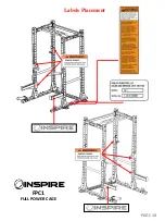
Page 18: ...PAGE 18 Labels Placement FPC1 FULL POWER CAGE ...

Page 19: ...PAGE 19 ...

Reviews: