background image


49 


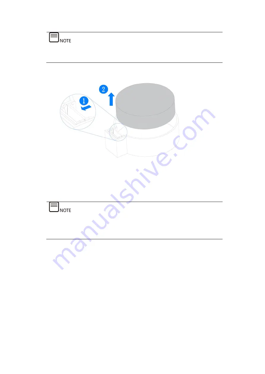
The drawings shown below are for illustration only. The location and orientation 
of the battery may differ depending on the models you purchased. 

Figure 5-1 Removing the CMOS Battery 


11.


Take the new battery out from the anti-static package. 

12.


Place the new battery into the socket, being careful to observe the correct 
polarity. 

13.


Snap the battery into place. Make sure the battery is secured within the socket. 


After replacing the battery, you must reconfigure the server and reset the system 

date and time. 


Summary of Contents for NF5266M6

Page 1: ...Inspur Server NF5266M6 User Manual Document Version V1 1 Release Date July 23 2021 ...

Page 2: ...y Meanwhile it is suggested to wipe the drive data thoroughly and securely with third party erasing tools The products services or features you purchased may obtain or use some personal data such as email address for alerts and IP address during operation or fault locating There should be user privacy policies in place with adequate measures implemented in accordance with the applicable laws to en...

Page 3: ...ly to your purchased model This manual is only used as a guide Inspur shall not be liable for any damage including but not limited to loss of profits loss of information interruption of business personal injury or any consequential damage incurred before during or after the use of our products Inspur assumes you have sufficient knowledge of servers and are well trained in protecting yourself from ...

Page 4: ... supplier contact your supplier directly if you purchased through Inspur direct sales stores call Inspur service hotline 1 844 860 0011 1 760 769 1847 for technical support For your safety please do not disassemble the server s components extend configuration or connect other peripherals arbitrarily You can contact Inspur for our support and guidance Before disassembling the server s components pl...

Page 5: ...ntial for serious injury or even death if not properly handled A potential for minor or moderate injury if not properly handled A potential loss of data or damage to equipment if not properly handled Operations or information that requires special attention to ensure successful installation or configuration Supplementary description of manual information Revision History Version Date Description o...

Page 6: ...Overview 10 3 1 Front Panel 10 3 1 1 24 3 5 inch Drive Configuration 10 3 2 Rear Panel 11 3 3 Buttons and LEDs 12 3 3 1 Front Panel Buttons and LEDs 12 3 3 2 Drive Tray LEDs 14 3 3 3 PSU LEDs 14 3 4 Interface Description 15 3 5 Motherboard View 15 3 6 Motherboard Jumper Introduction 16 3 7 System Layout 18 4 Getting Started 19 4 1 Installing Server into the Rack 19 4 1 1 Installing Cage Nuts 19 4 ...

Page 7: ...ot swap 2 5 3 5 inch Drive Replacement 38 4 4 10 Hot Swap PSU Replacement 43 4 4 11 OCP NIC Replacement 44 4 4 12 E1 S SSD Replacement 45 4 5 Firmware Update and Configuration 47 4 6 Cable Routing 47 5 Battery Replacement 48 6 Electrostatic Discharge 50 6 1 Preventing Electrostatic Discharge 50 6 2 Grounding Methods to Prevent Electrostatic Discharge 50 7 Troubleshooting 52 7 1 Hardware Problems 5...

Page 8: ...emperature 60 8 2 Vibration and Shock Resistance 60 8 3 Altitude and Air Pressure 61 8 4 Alternating Temperature and Humidity 61 8 5 Extended Operation Temperature 61 8 6 Extended Operation Temperature Limits 61 8 7 Thermal Restrictions 62 8 8 Operational Requirement 62 8 9 EMC Requirements 65 8 10 Power Supply Requirements 67 8 10 1 AC Power Supply Requirement 67 8 10 2 DC Power Supply Requiremen...

Page 9: ... 10 7 DC Power Supply 70 9 Warranty 71 9 1 Warranty Service 71 9 2 Inspur Service SLA 73 9 3 Warranty Exclusions 73 Appendix 75 Drive Neodymium Content Reference Table 75 A 1 A 2 Acronyms and Abbreviations 76 ...

Page 10: ...rrent limit for the extension cable Please be sure to use the power supply components that come with the server such as power cords power socket if provided with the server etc For your safety and safety of the equipment please do not replace power cords or plugs randomly To prevent electric shocks caused by leakage in the system please make sure that the power cables of the system and peripherals...

Page 11: ...lizers before installing the equipment into the cabinet After installing the equipment and other components into the cabinet only one component can be pulled out from the cabinet through its sliding part at one time Pulling out several components at the same time may cause the cabinet to turn over resulting in serious personal injury Please do not move the cabinet on your own Considering the heigh...

Page 12: ...uipment please pay attention to the followings In case of lightning please do not connect or use the modem Never connect or use the modem in a damp environment Never insert the modem or telephone cables into the socket of network interface controller NIC Before unpacking the product package accessing or installing internal components or touching uninsulated cables or jacks of the modem please disc...

Page 13: ...ouch the components or connectors on the plug in cards When handling the plug in cards or components firmly grab the edges of the plug in cards or those of components or their metal retaining brackets During cabinet installation and application please pay attention to the followings After the cabinet has been installed please ensure that the stabilizer feet have been fixed into the rack and suppor...

Page 14: ...es NF5266M6 is built on the 3rd generation Intel Xeon Scalable processors Each CPU communicates with each other via 3 UPI links at 11 2 GT s A single CPU supports up to 40 cores 1 5 MB L3 cache per core and 80 threads with the max Turbo frequency at 4 3 GHz and TDP at up to 220 W enabling powerful parallel processing capabilities 16 DDR4 ECC memory modules 3200 MT s RDIMMs and LRDIMMs offering a m...

Page 15: ...0 Series processor s Up to 40 cores 3 1 GHz Max Turbo frequency up to 4 3 GHz 4 cores Three UPI links Up to 11 2 GT s L3 cache up to 1 5 MB single core Thermal design power up to 220 W Chipset Intel C621A Integrated Display Controller Integrated in BMC Aspeed 2600 up to 1280 1024 resolution Memory Up to 16 memories Each processor supports 8 memory channels Each channel supports 1 memory slot Speed...

Page 16: ...ntroller card controls all SAS SATA drives NVMe drives can be directly connected to the CPU Network One onboard OCP 3 0 NIC module and one scalable OCP 3 0 NIC module 1 Gb s 10 Gb s 25 Gb s 100 Gb s 200 Gb s Standard 1 Gb 10 Gb 25 Gb 40 Gb 100 Gb NICs I O Expansion Two drive chassis Up to 6 standard PCIe expansion cards and up to 1 OCP 3 0 NIC Two PCIe 4 0 x16 half height half length cards Four PC...

Page 17: ...tegrated with 1 independent 1000 Mbps network interface dedicated for IPMI remote management Operating System Microsoft Windows Server 2016 2019 Red Hat Enterprise Linux 7 8 SUSE Linux Enterprise Server 12 15 CentOS Enterprise Linux 7 8 Chassis Dimensions With mounting ears 482 87 5 891 2 mm 18 98 3 44 35 09 inch Width Height Depth Without mounting ears 447 87 5 866 mm 17 60 3 44 34 09 inch Width ...

Page 18: ...ure 5 C 35 C 41 F 95 F at 0 914 m 0 3000 ft Operating temperature 10 C 32 50 F 89 6 F at 914 2133 m 3000 7000 ft Noise Idle 79 db Operating 89 db 2 3 Power Efficiency Table 2 2 Power Efficiency of Platinum Power Supplies Rated Power 10 Load 20 Load 50 Load 100 Load PF 50 Load 1300 W 90 94 91 0 98 1600 W 90 94 91 0 98 Table 2 3 Power Efficiency of Titanium Power Supplies Rated Power 10 Load 20 Load...

Page 19: ...24 3 5 inch Drive Configuration Figure 3 1 Front Panel of 24 3 5 inch Drive Configuration Item Feature 1 Power Button 2 Top layer Drive Drawer 3 Mid layer Drive Drawer 4 Bottom layer Drive Drawer 5 Quick Release Lever 6 UID BMC RST button 7 LEDs ...

Page 20: ...11 3 2 Rear Panel Figure 3 2 Rear Panel ...

Page 21: ...1 18 2 5 inch Drive 4 9 PSU0 19 E1 S SSD 8 10 OCP 3 0 NIC 3 3 Buttons and LEDs 3 3 1 Front Panel Buttons and LEDs Table 3 1 Front Panel Buttons and LEDs Item Icon Feature Description 1 Power Button Solid green Power on state Solid orange Standby state Long press 4 seconds to force a shutdown 2 System Status LED Off Normal Solid red A failure occurs Flashing red A warning occurs 3 Memory Status LED...

Page 22: ...eat LED Off Normal Solid red CPU Memory overheats 7 Bottom layer Drive Status LED Solid green Normal Solid red Drive failure 8 Mid layer Drive Status LED Solid green Normal Solid red Drive failure 9 Top layer Drive Status LED Solid green Normal Solid red Drive failure 8 UID BMC RST Button Solid blue UID is turned on manually or in the OS Flashing blue KVM has been launched or firmware update in pr...

Page 23: ... LEDs Item PSU LED Status Description 1 Solid green Normal 2 Off No AC power to PSU 3 Solid amber A shutdown has occurred when the protection mechanism had been triggered 4 Flashing amber at 1 Hz PSU continues operating after a warning event has occurred 5 Flashing green at 1 Hz PSU operates in standby mode with AC input 6 Flashing green at 0 33 Hz on for 2 seconds and off for 1 second PSU operate...

Page 24: ...u to connect a USB device to the system Note Make sure the USB device is in good condition as it may cause the server to work abnormally BMC Management Network Port Enables you to manage the server Note The port is a Gigabit Ethernet port of 100 1000M self adaption Debug Serial Port Enables you to debug and monitor the system status 3 5 Motherboard View Figure 3 4 Motherboard Connectors ...

Page 25: ...g Connector 25 CPU0 Riser High Speed Signal Connector 9 Fan Connectors 26 CPU0 Riser Power Connector 10 RAID Key Connector 27 VPP Bus Connector 11 Slimline x8 Connector SFF 8654 Connector 28 VGA Connector 12 Left Ear Connector 29 USB 3 0 Connector 2 13 I2 C Connector 30 1000M Network Port 14 3 5 Front Backplane Power Connector 8 31 Serial Port Connector 15 EXP Card Power Connector 32 UID Button 16...

Page 26: ...ble from the electrical outlet 2 Wait for 5 seconds 3 Locate the CLR_CMOS jumper cap on the motherboard 4 Move the jumper cap from the default pins 1 2 to pins 2 3 5 Plug in the power cable and power on the server and then wait for 10 seconds for the CMOS to clear 6 Power down the server unplug the power cable and then wait for 5 seconds again 7 Move the jumper cap back to the default pins 1 2 8 R...

Page 27: ...Diagram Item Feature Item Feature 1 Front Drive Drawer 3 8 OCP 3 0 NIC 2 PHMs 9 Rear PCIe Riser Card Assembly 3 Motherboard 10 Access Panel 4 Rear Drive Backplane 11 Chassis 5 Air Duct 12 Fan Modules 6 Rear Drive Modules 13 Access Panel 7 PSUs ...

Page 28: ... properly The loading bearing capacity of non Inspur rails must be higher than 100 kg If not you MUST use Inspur supplied rails as using these non Inspur rails may cause such risks as installation failure Inspur will not assume any responsibility or liability for any damage or injury caused by this To reduce the risk of personal injury or damage to the equipment DO secure the mounting ears to the ...

Page 29: ...ble from the server To reduce the risk of personal injury electric shock or damage to the equipment remove the power cord to disconnect power from the server The power button does not shut off the system power completely Some power supplies and internal circuitry remain active until AC power is removed 4 3 Pre Disassembly Instructions Read the installation instructions for all the hardware operati...

Page 30: ...hen sliding the server into the rack The sliding rails could pinch your fingers a Open the quick release levers of the mounting ears on the front panel of the server and then loosen the two captive screws in the levers securing the server in place b Gently slide and remove the server out of the rack Figure 4 2 Removing the Server out of the Rack After performing installation or maintenance slide t...

Page 31: ...nstallation process Item appearance may be different on actual models 4 4 1 Access Panel Replacement To reduce the risk of personal injury from hot surfaces allow the drives and the internal system components to cool before touching For proper cooling do not operate the server without the access panel air duct or fans installed If the server supports hot swap components minimize the amount of time...

Page 32: ... front of the server until it closes 3 Tighten the two captive screws on the rear of the server securing the access panel to the server clockwise 4 4 2 Super Capacitor Replacement To remove the super capacitor 1 Remove the access panel 2 Disconnect the cable of the super capacitor 3 Undo the velcro of the super capacitor 4 Remove and put the super capacitor into an antistatic bag Figure 4 4 Removi...

Page 33: ...citor 4 Install the access panel 4 4 3 Air Duct Replacement For proper cooling do not operate the server without the access panel air ducts expansion slot covers or blanks installed If the server supports hot swap components minimize the amount of time the access panel is open To remove the air duct 1 Remove the access panel 2 Remove the super capacitor on the air duct 3 Lift up the air duct as in...

Page 34: ... Install the access panel 4 4 4 Hot Swap Fan Module Replacement To remove the fan module 1 Remove the access panel 2 Remove the fan module a Squeeze the circular release tabs towards each other and then lift up the fan module out of the fan bay b Put the fan module in an antistatic bag Figure 4 7 Removing the Fan Module To install the fan module ...

Page 35: ...the Fan Module 3 Install the access panel 4 Verify that the fan status LED is off 4 4 5 Onboard M 2 SSD Replacement To remove the M 2 SSD 1 Remove the access panel 2 Disconnect the cable of the super capacitor 3 Remove the air duct 4 Open the latch securing M 2 SSD in place and one side of the SSD pops up Figure 4 9 Opening the Latch of the M 2 SSD 5 Tilt and pull out the M 2 SSD Put it into an an...

Page 36: ...he antistatic bag 2 Tilt the M 2 SSD a little and insert it into the slot Figure 4 11 Installing the M 2 SSD 3 Secure the M 2 SSD onto the board with the latch Figure 4 12 Installing the M 2 SSD Latch 4 Install the air duct 5 Connect the cable of the super capacitor 6 Install the access panel ...

Page 37: ...able of the super capacitor 3 Remove the air duct 4 Locate the DIMM you want to replace 5 Remove the DIMM a Push the release tabs on both ends of the DIMM slot outward to unlock it Gently lift and remove the DIMM from the slot Make sure the release tabs on both ends of the DIMM slot are fully opened Figure 4 13 Removing the DIMM b Put it into the memory box To install the DIMM 1 Take the new DIMM ...

Page 38: ...per capacitor 5 Install the access panel Figure 4 15 DIMM Slot Layout Detailed DIMM population and combination principles are as follows BPS need to be used with DDR4 DIMMs In the following figure D stands for DDR4 DIMMs B for BPS and iMC for Integrated Memory Controller Only DIMMs of the same type could be used in the same machine Detailed DIMM population and combination principles are as follows...

Page 39: ...tsink Module PHM Replacement The server supports single or dual processor configuration depending on the model you purchased To help avoid damage to the processor and motherboard do not install the processor without using the processor installation tool To prevent possible server malfunction and damage to the equipment multiprocessor configurations must contain processors with the same part number...

Page 40: ...own on the heatsink label with a T30 Torx screwdriver b Push the four lock in wires inward to unlocked position with both hands simultaneously c Gently lift the PHM off the CPU socket Figure 4 16 Removing the PHM Use a protective cover to protect the CPU socket to avoid damaging socket pins after the PHM has been removed The gold pins on the CPU are fragile and can be easily damaged if touched Dur...

Page 41: ...g the CPU to the Carrier Clip Gently remove the CPU and put it into an antistatic bag Figure 4 17 Removing the CPU 7 Remove the CPUCarrier Clip a Close the CPU lever b Push to release the retaining tab near the printed triangle c Release the rest three tabs d Gently lift the CPU Carrier Clip off the heatsink ...

Page 42: ...Coat thermal grease evenly onto the heatsink before reusing the heatsink To install the PHM 1 Install the CPU Carrier Clip a With the heatsink thermal grease side up align the triangle mark on the Carrier Clip with that on the heatsink label b Install the Carrier Clip onto the heatsink until the four retaining tabs of the Carrier Clip snap into place ...

Page 43: ... the CPU a With the gold pins up align the triangle mark on the CPU with that on the Carrier Clip b Grasp CPU by its two edges and install it into the Carrier Clip Make sure the notches of the CPU are aligned with the retaining tabs of the Carrier Clip and the CPU is secured in place by the tabs on the four sides of the Carrier Clip ...

Page 44: ...sly 7 Tighten the four screws securing the PHM to the CPU socket clockwise in the sequence as shown on the heatsink label with a T30 Torx screwdriver 8 Install the air duct 9 Connect the cable of the super capacitor 10 Install the access panel 4 4 8 PCIe Expansion Card Replacement To prevent damage to the server or expansion cards power down the server and remove all power cables before removing o...

Page 45: ...odel you purchased To remove the PCIe expansion card 1 Remove the access panel 2 Loosen the captive screw anticlockwise with a Phillips screwdriver Gently lift and remove the PCIe Riser card assembly with both hands Be sure to apply even force Figure 4 21 Removing the PCIe Riser Card Assembly 3 Loosen the screw on the cover plate to remove it ...

Page 46: ...rom the antistatic bag 2 Align and insert the PCIe card to the Riser card slot 3 Close the cover plate Install and tighten the screw to secure it in place 4 Align and insert the Riser card to the slot on the motherboard 5 Tighten the captive screw clockwise with a Phillips screwdriver Insert the PCIe Riser card assembly onto the motherboard Be sure to apply even force 6 Install the access panel ...

Page 47: ... the amount of time the access panel is open 1 Front Panel 24 3 5 inch Drive To remove the drive 1 Press the blue latches on both sides of the drawer inward The drawer handles pop up Hold the handles with both hands to slide the drawer out Figure 4 24 Pulling out the Drive Drawer 2 Push the latch as indicated by the silkscreen arrow The drive tray handle pops up Hold the handle to remove the drive...

Page 48: ...39 Figure 4 25 Removing the Drive Module 3 Remove the drive tray as indicated by the figure to remove the drive Figure 4 26 Releasing the Drive Tray ...

Page 49: ...all the drive 1 Install the drive to the drive tray 2 Install the drive module into the drive drawer Rotate the handle downward until it clicks into place Figure 4 28 Closing the Tray Handle 3 Slide the drawer in Press the handles to close it ...

Page 50: ...el 2 5 3 5 inch Drive To remove the drive 1 Remove the hot swap drive a Press the release latch to release the lever The lever will pop up automatically Figure 4 30 Pressing the Release Latch b Hold the lever and pull the drive module out of the drive bay ...

Page 51: ... 4 32 Removing Screws Securing the Drive to the Drive Tray To install the drive 1 Install the drive to the drive tray a Orient the drive to the drive tray with the drive connector facing the rear end of the tray b Tighten the four screws securing the drive to the drive tray clockwise with a Phillips screwdriver 2 Insert the drive module into the drive bay with the lever in the open position ...

Page 52: ...r supply or power supply blank to cool before touching To prevent improper cooling and thermal damage do not operate the server unless all bays are populated with either a component or a blank To remove the PSU 1 Grasp the handle and press on the blue lever to release the PSU Pull the PSU out of the power supply bay Figure 4 33 Removing the PSU 2 Put it into an antistatic bag To install the PSU 1 ...

Page 53: ... damage to the server or expansion boards power down the server and remove all power cables before removing or installing the OCP NIC To remove the OCP NIC 1 Loosen the thumbscrew securing the OCP NIC to the chassis anticlockwise Figure 4 34 Loosening the Thumbscrew 2 Pull the OCP NIC horizontally out of the chassis Figure 4 35 Removing the OCP NIC 3 Put it into an antistatic bag ...

Page 54: ...t snaps into place 3 Tighten the thumbscrew securing the card to the chassis clockwise 4 4 12 E1 S SSD Replacement To remove the E1 S SSD 1 Press the release latch to release the lever The lever will pop up automatically Figure 4 36 Pressing the Release Latch 2 Hold the lever and pull the E1 S SSD module out of the drive bay ...

Page 55: ...p and remove the E1 S SSD from the tray Figure 4 38 Remove the E1 S SSD To install the E1 S SSD 1 Align the four screws with the screw holes insert the four screws into the holes 2 Tighten the four screws 3 Fully open the lever Install the E1 S SSD module into the chassis and close the lever to secure the module in place ...

Page 56: ...llection and Analysis Guide BMC Update Manual 4 6 Cable Routing Blue indicates the data cable routing between the backplane and SAS RAID card Red indicates the cable routing between the backplane power connector and the motherboard power connector for powering the drives Please route cables based on the purchased machine configuration Figure 4 39 Front 24 LFF Rear 2 LFF 2 NVMe ...

Page 57: ...ti static gloves To replace the battery 1 Power off the server and disconnect all the power cables to remove power completely 2 Gently slide and remove the server out of the rack 3 Remove the access panel 4 Remove the air duct 5 Remove the OCP 3 0 NIC 6 Remove any full length expansion card if the card is in the way 7 Locate the CMOS battery 8 Gently press the clip on the battery socket until the ...

Page 58: ...re 5 1 Removing the CMOS Battery 11 Take the new battery out from the anti static package 12 Place the new battery into the socket being careful to observe the correct polarity 13 Snap the battery into place Make sure the battery is secured within the socket After replacing the battery you must reconfigure the server and reset the system date and time ...

Page 59: ...Always be properly grounded when touching a static sensitive component or assembly 6 2 Grounding Methods to Prevent Electrostatic Discharge Several methods are used for grounding Use one or more of the following methods when handling or installing electrostatic sensitive parts Use a wrist strap connected by a ground cord to a grounded workstation or computer chassis Wrist straps are flexible strap...

Page 60: ...51 For more information on static electricity or assistance with product installation contact Inspur Customer Service ...

Page 61: ...off or amber maybe the PSUs are faulty Please replace the faulty PSUs with PSUs of the same server model and of the same specifications to test whether the PSUs have failed the PSU LEDs turn green but the power LED on the power button is still orange please call Inspur Customer Service Hotline 1 844 860 0011 1 760 769 1847 or email to serversupport inspur com 2 All the PSU LEDs are green a If all ...

Page 62: ... the instructions above do not resolve the problem please call Inspur Customer Service Hotline 1 844 860 0011 1 760 769 1847 or email to serversupport inspur com and inform us of the detailed warning information and failure 7 1 3 Abnormal LED on the Front Panel Symptoms The status LED on the front panel illuminates red Solutions Identify the abnormal LED based on Front Panel Buttons and LEDs 1 If ...

Page 63: ...ce please confirm if OS is installed successfully and OS boot order is set to first 2 If the stuck interface includes directional error information of hardware such as self test errors of memory and RAID record the detailed errors 3 If the stuck interface is the POST interface and there are errors reported in the interface please record the detailed errors 4 If the instructions above do not resolv...

Page 64: ...onfigured with an RAID card you can also choose to log into the RAID management interface to check whether there is a drive failure 4 If there is a drive failure or the instructions above do not resolve the problem please call Inspur Customer Service Hotline 1 844 860 0011 1 760 769 1847 or email to serversupport inspur com Hot swap storage drive allows users to remove or replace the drive without...

Page 65: ...b interface to see if all the fans are identified and if the fan mode is automatic 6 If the instructions above do not resolve the problem please call Inspur Customer Service Hotline 1 844 860 0011 1 760 769 1847 or email to serversupport inspur com 7 1 8 Alarm Sound from the Server Symptoms There is an alarm sound during server startup or operation Solutions Find the source of the alarm sound 1 If...

Page 66: ...nector on the motherboard is faulty Please call Inspur Customer Service Hotline 1 844 860 0011 1 760 769 1847 or email to serversupport inspur com 7 1 10 USB Port Problem Symptoms Unable to use devices with a USB port Solutions 1 Make sure the OS of the server supports USB devices 2 Make sure the server has been installed with the correct USB driver and try installing the USB driver again 3 Connec...

Page 67: ... the Windows OS turn down the virtual memory or allocate the virtual memory to other partitions 4 If the instructions above do not resolve the problem please call Inspur Customer Service Hotline 1 844 860 0011 1 760 769 1847 or email to serversupport inspur com 7 2 2 PXE Boot Failure Symptoms Unable to install OS via PXE Solutions 1 Check if the PXE server can be used to install OS for another ser...

Page 68: ...s lower than the actual rate of the network port under the server OS Solutions 1 Check whether the network cable is connected properly and whether the network port LED flashes normally to ensure that the network is configured correctly 2 Unplug and plug the network cable back to see if the problem can be solved If not connect the server with a laptop via a known working network cable If the networ...

Page 69: ...y is 5 to 95 and the atmosphere must be non condensing all the time 8 2 Vibration and Shock Resistance Table 8 2 Vibration and Shock Resistance Parameter Condition Requirement Vibration Operating 5 500 Hz 0 21 Grms X Y and Z axis and every direction for 15 minutes Transportation Storage 5 500Hz 2 2 Grms X Y and Z axis and every direction for 10 minutes Shock Operating On negative and positive X Y ...

Page 70: ... point is 39 C 102 2 F relative humidity is 5 to 95 and the atmosphere must be non condensing all the time 8 5 Extended Operation Temperature Table 8 5 Extended Operation Temperature Temperature Specification Numbers are for instance only Description 5 35 41 F 95 F 5 85 RH Note1 Continuous running is possible 5 35 41 F 95 F 5 90 RH Note2 Running time 1 per year Note 1 The system performance will b...

Page 71: ...AS drives 35 95 F NVDIMM drives 30 86 F 4 Drive configuration 24 3 5 No higher than 220 W 1U 2U 6038 SAS drives 35 95 F NVDIMM drives 30 86 F 2 Drive configuration 24 3 5 No higher than 220 W 1U 2U 6056 SAS drives 35 95 F NVDIMM drives 30 86 F 2 LFF drive configuration 24 3 5 No higher than 165 W 1U 6056 SAS drives 35 95 F NVDIMM drives 30 86 F 8 E1 S SSD configuration 24 3 5 No higher than 185 W ...

Page 72: ...hemical reactions may occur due to long term contact between these mixed corrosive gas pollutants or pollutants of one single corrosive gas and other environmental factors such as temperature or relative humidity which may pose a risk of IT equipment failure from corrosion and damage circuit boards of IT equipment and system component units with weak oxidation resistance This article specifies the...

Page 73: ...be a factor in determining equipment reliability G3 harsh 2000 Å month 2000 Å month An environment in which there is high probability that corrosive attack will occur GX severe 2000 Å month 2000 Å month An environment in which only specially designed and packaged equipment would be expected to survive See the table below for the requirements on the copper and silver corrosion rates Table 8 8 Conce...

Page 74: ...ble and corrosive dust The table below lists the requirements for concentration of the mechanically active materials in the server room Table 8 9 Requirements for Concentration of Mechanically Active Materials Mechanically Active Materials Unit Concentration Sand mg m3 30 Suspending dust mg m3 0 2 Dust deposit mg m2 h 1 5 To meet these requirements take the following measures in the server room Us...

Page 75: ...emissions broadcast radar mobile communication transmitters electrified railways industrial radiation substations and high voltage transmission lines The interference effect of other equipment in the server room must comply with relevant standards and regulations Take measures to shield and isolate natural noise such as atmospheric noise and solar radio noise when necessary To avoid damage to the ...

Page 76: ...re mode AC power supply system should work under nominal voltage and rated frequency Table 8 11 Nominal Voltage and Rated Frequency Nominal Voltage Rated Frequency 110 V 208 V 60 Hz 220 V 380 V 50 Hz A UPS is typically used as an AC potential power of network products A UPS should be in the same phase as the mains supply The time used for switching between the UPS and the mains supply should be le...

Page 77: ...ode for Design of Data Centers GB50174 Connect two storage battery strings in parallel A second UPS is needed as redundant backup 8 10 4 HVDC Power Supply The high voltage direct current HVDC system can eliminate the problems existing in conventional AC and low voltage DC power supplies At present 240 V HVDC standards and 336 V HVDC standards are the mainstream HVDC standards used in China 8 10 5 ...

Page 78: ... reaches the specified threshold the power supply system automatically reduces the power or shuts down the power amplifier When the temperature falls below the threshold the power supply system restores the normal power output The system provides alarm records and query and the alarm display can be updated on a real time basis The alarm information is protected against loss when the system is out ...

Page 79: ...e diameters of all power cords meet the requirements for wire ampacity 8 10 7 DC Power Supply The DC power supply should be stable and reliable The power equipment should be deployed near the server The standard DC voltage is 48 VDC with a fluctuation range of server power between 40 V to 72 V ...

Page 80: ...Warranty Service Type and Duration Type Duration Remote Technical Support 3 years RMA Services 3 years The 24 7 remote technical support can be obtained through hotline e mail and Service Portal 1 Through hotline and e mail support Inspur engineers help customers diagnose the cause of malfunction and provide solution Service Portal 1 provides access to firmware customized update files and related ...

Page 81: ...ted to be free of defects in material or workmanship for ninety 90 calendar days or for the remainder of the warranty period of the product whichever is longer Advance Replacement Under the terms of Advance Replacement Service if a problem with customer product cannot be resolved via hotline and e mail support and a replacement part is required Inspur will ship out replacement part s in advance wi...

Page 82: ...re Products The Warranty Terms Conditions do not apply to consumable parts as well as any products that the serial number missed damaged or obscured for the following reasons Accident misuse abuse defiling improper maintenance or calibration or other external causes Operating beyond the parameters as stipulated in the user documentation Use of the software interface parts or supplies not provided ...

Page 83: ... has reached its write endurance limit In no event will Inspur be liable for any direct loss of use interruption of business lost profits lost data or indirect special incidental or consequential damages of any kind regardless of the form of action whether in contract tort including negligence strict liability or otherwise even if Inspur has been advised of the possibility of such damage and wheth...

Page 84: ...ies Name Neodymium Content Range 5 g 5 g 25 g 25 g Cimarron 2T 4T Cimarron 6T 8T Evans Kestrel MakaraBP MakaraPLUS Mobula MobulaBP Skybolt Tatsu Table A 1 2 WD Drive Neodymium Content Reference Range Product Series Name Neodymium Content Range 5 g 5 g 25 g 25 g Rainier Libra He10 Leo A Vela A Vela AP Hs14 Leo B Paris C Vela AX ...

Page 85: ...A MG06 SAS MG06 SATA MG07 SAS MG07 SATA MG08 16T A 2 Acronyms and Abbreviations A AC Alternating Current ACPI Advanced Configuration and Power Management Interface AES Advanced Encryption Standard New Instruction Set AI Artificial Intelligence AOC Active Optical Cables API Application Program Interface ARP Address Resolution Protocol B BIOS Basic Input Output System BMC Baseboard Management Contro...

Page 86: ...ocessing Unit CRPS Common Redundant Power Supplies CRU Customer Replaceable Unit CSA Canadian Standards Association CSM Compatibility Support Module D DC Direct Current DDR4 Double Date Rate 4 DHCP Dynamic Host Configuration Protocol DIMM Dual Inline Memory Modules DNS Domain Name System DVD Digital Video Disc F FMA Failure Mode Analysis FRU Field Replaceable Unit ...

Page 87: ... Disk Drive HTML Hyper Text Markup Language HWRAID Hardware Redundant Arrays of Independent Drives I I O Input Output IEC International Electrotechnical Commission IOPS Input Output Operations Per Second IP Internet Protocol IPMB Intelligent Platform Management Bus IPMI Intelligent Platform Management Interface iSCSI Internet Small Computer System Interface ...

Page 88: ...Light Emitting Diode LRDIMM Load Reduced Dual In Lane Memory Module M MLAN Music Local Area Network N NCSI National Communication System Instructions NEMA National Electrical Manufacturers Association NFPA National Fire Protection Association NIC Network Interface Controller NM Node Manager NPU Network Processing Unit ...

Page 89: ...erating System P PCH Platform Controller Hub PCI Peripheral Component Interconnect PCIe Peripheral Component Interconnect express PDU Power Distribution Unit PFR Platform Firmware Resilience PHM Processor Heatsink Module PHY Physical PMBus Power Management Bus POST Power On Self Test PSU Power Supply Unit PXE Pre boot Execution Environment R ...

Page 90: ... Clock S SAS Serial Attached Small Computer System Interface SATA Serial Advanced Technology Attachment SFP Small Form factor Pluggable SIC Smart Interface Card SKU Stock Keeping Unit SMTP Simple Mail Transfer Protocol SNMP Simple Network Management Protocol SOL Serial Over LAN SSD Solid State Disk SSH Secure Shell SWRAID Software Redundant Arrays of Independent Drives T ...

Page 91: ...n Power TPCM Trusted Platform Control Module TPM Trusted Platform Module U UEFI Unified Extensible Firmware Interface UID User Identification UPI Ultra Path Interconnect UPS Uninterruptible Power Supply USB Universal Serial Bus V VGA Video Graphics Array VLAN Virtual Local Area Network X XDP eXtend Debug Port ...

Reviews: