11
Component Identification
Figure 3-2
Item
Description
1
Power button
2
UID│RST button
3
System failure LED
4
Memory failure LED
5
Fan failure LED
6
Power failure LED
7
System overheat LED
8
Network status LED
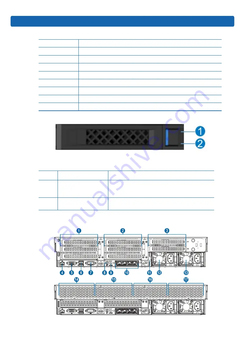
HDD Tray LEDs
Figure 3-4
Figure 3-3
Item
Description
Status & Interpretation
1
Fault alarm LED
Steady red: An HDD failure occurs
Steady blue: HDD positioning
Steady pink: RAID rebuilding
2
Activity status LED
Steady green: Normal
Flashing green: Read and write activity
3.2 Rear Panel Components
Figure 3-5
Summary of Contents for NF8260M5
Page 1: ...Inspur Server User Manual NF8260M5 ...
Page 35: ...29 Hardware Options Installation Figure 6 4 DIMM population guidelines Figure 6 5 ...
Page 59: ...53 BIOS Setup Figure 7 33 Figure 7 34 ...
Page 98: ...92 Figure 7 74 Figure 7 75 ...
Page 126: ...120 chassis Figure 8 8 Chassis user Figure 8 9 User mc Figure 8 10 MC ...
Page 127: ...121 BMC Settings fan Figure 8 11 Fan psu Figure 8 12 Psu id Figure 8 13 Id diagnose ...
Page 178: ...172 Figure 8 58 SOL Setting in BIOS Figure 8 59 Default Serial Setting ...


