- 12 -
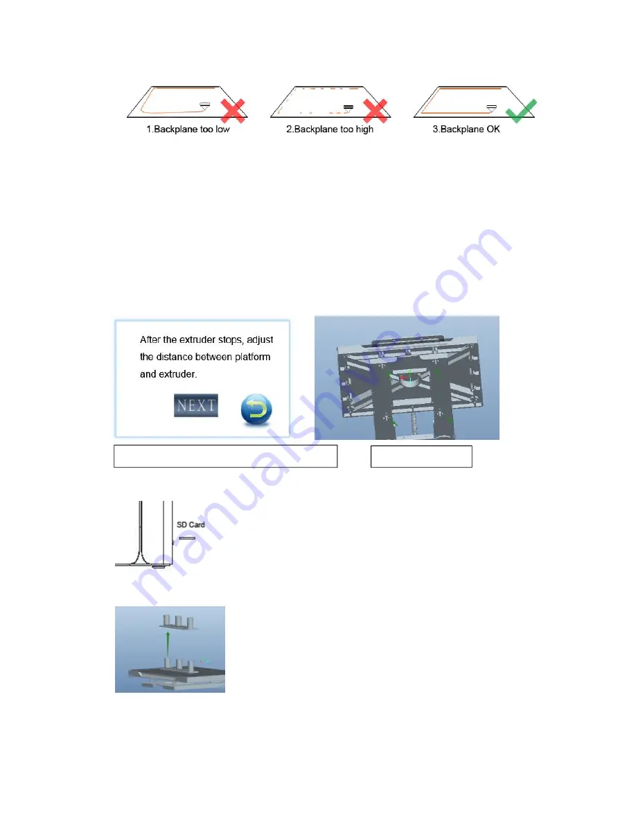
Level adjustment interface on the monitor
Figure 1
Leveling method:
As shown in Figure 2, the print platform can be raised or lowered by rotating the
bottom of the four knobs to achieve. From the bottom-up perspective, clockwise rotation makes the plat
lower, and counterclockwise rotation makes floor elevation.
Leveling steps:
Rotate the four knobs clockwise, so that the printing platform and the nozzle has a
3-5mm gap;
Put an A4 paper on the printing platform, select TOOLS
→
LEVELING, the
interface displays as shown in Figure 1. Rotate the knob corresponding position of
the nozzle counterclockwise, while swinging A4 paper, when you feel significant
resistance between it and the nozzle, but still easy to swing, stop rotating the
knob, the position is the best leveling position, then click NEXT, repeat the
operation until the main interface says LEVELING SUCCESSFULLY.
4) Model Printing
Copy the already converted GCODE model file to the SD card (the standard
SD card already contains 3 test models). The SD card as shown in the left
Figure. Insert the SD card to the slot with gold finger side up, then select the
Print menu, in the file directory list, select the file you want to print, and wait
for printing to complete.
5) Printing completed
After the model has been printed, wear gloves and use a model blade to
carefully shovel the model down. If the model is braced, remove it
manually or immerse it in special solvent DISSOLUBLE for
approximately 2-5 hours . (The dissolution time is estimated based on the
model structure, and the model with internal cavity supports is longer.)
Warnings for solvent:
DISSOLUBLE solvent is flammable; place in where the child can not reach;
do not eat; do not upside down to prevent solvent leakage. Storage of the product in sealed, cool and
dry condition.
Level knob
Figure 2
Summary of Contents for INVENTOR PRO
Page 1: ...FDM 3D Printer INVENTOR PRO Yiwu Instone 3D Technology Co Ltd USER S MANUAL ...
Page 6: ... 6 Get to know your INVENTOR PRO ...
Page 8: ... 8 Brief Introduction of User Interface Logical Relationship HOMEPAGE SYSTEM ...
Page 10: ... 10 FILAMENT LEVEL FAN WORKING CONDITION INFO WIFI ...
Page 14: ... 14 2 Basic settings ...
Page 15: ... 15 3 Advanced parameters instruction ...
Page 16: ... 16 4 Expert Settings ...
Page 17: ... 17 5 Load model file 6 Rotate ...
Page 18: ... 18 7 Scale 8 Mirror 9 Right mouse menu ...


