background image

© Intatec Ltd 2009

2

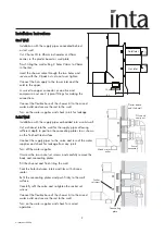
Installation Instructions

Stud Wall

Installation with the supply pipes concealed behind 
a stud wall.

Cut 2 holes 24 to 26mm in diameter at 45mm 
centres in the plaster board or wall plate. 

Finish tiling the wall cutting 2 holes 24mm to 26mm 
in the tiles.

Insert the shower valve through the two holes and 
secure with the 2 back nuts, do not over tighten.

Connect the hot supply to the lower inlet and the 
cold to the upper.

A swivel to copper connector or an olive and 
compression nut are 2 typical fittings for making the 
connections.

Connect the flexible hose of the shower kit to the mixed 
water outlet and secure the rail to the wall.

Turn on the water supplies and check joints for leakage.

Solid Wall

Installation with the supply pipes embedded into a solid wall.

Cut a channel into the wall for the supply pipes allowing 
sufficient depth to position the concealing plates to as shown 
on the finished tiled surface.

Connect the supply pipes to the  valve and turn of the water 
supplies and check for leakage from any joints.

Turn off the water supplies.

Unscrew the two socket set screws and carefully remove the 
body and concealing plates. 

Fill the channel and finish tiling the wall.

Seal the holes between inlets and tiles with silicone 
sealer.

Refit the concealing plates and push firmly to the wall 
surface.

Carefully refit the valve and re-tighten the socket set 
screws.

Connect the flexible hose of the shower kit to the mixed
water outlet and secure the rail to the wall.

Turn on the water supplies and check for correct 
operation.  

Plaster board 
and tiled wall

Swivel

connector

Olive and

comp. nut

Socket 

set screw

Concealing

plate

Mixed water

outlet

82

40

145

45 

Ctr

5

G

1/2

B

G

1

/

2

B

G

1

/

2

B

Cold Inlet

Hot Inlet

19.5

Summary of Contents for 10019CP

Page 1: ...tion as accurate as possible We cannot accept any responsibility should it be found that in any respect the information is inaccurate or incomplete or becomes so as a result of further developments or...

Page 2: ...ters and unbalanced supplies i e cold mains tank fed hot They are not suitable for non modulating combination boilers Designated Pressure LP HP Max Static Pressure 10 bar Temperature Stability 2 C Inl...

Page 3: ...o a solid wall Cut a channel into the wall for the supply pipes allowing sufficient depth to position the concealing plates to as shown on the finished tiled surface Connect the supply pipes to the va...

Page 4: ...out of the body If any of the O ring seals or the thermostatic element is blocked or damaged they must be replaced Using neutral silicon grease re lubricate the internal moving components of the valve...

Page 5: ...on is required when the thermostatic shower valve is used in a TMV2 Applications under the requirements of BS EN 1111 1999 Sanitary tapware Thermostatic Mixing Valve PN 10 General Technical Specificat...

Page 6: ...nstaller of the thermostatic shower valve must comply with the requirements of the Water supply Water Fittings Regulations 1999 and also be aware of their responsibility and duty of care to ensure tha...

Page 7: ...s and strainers 9 The fitting of isolation valves is required as close as is practicable to the water supply inlets of the thermostatic shower valve 10 The fitting of strainers is recommended as close...

Page 8: ...are met proceed to set the temperature as stipulated in the manufacturer s installation instructions 4 3 Measure and record the temperature of the hot and cold water supplies at the connection to the...

Page 9: ...no significant change to the set outlet temperature 2 C or less from the original settings and the fail safe shut off is functioning then the valve is working correctly and no further service work is...

Reviews: