Page 7
05/20 E&OE
Section 5
-
Installation
5.2
Pipework Connections
District
’
Inlet and Outlet –
3/4"
Male BSP
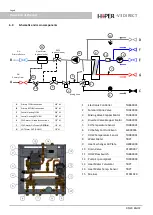
These are situated at the top of the station, with inlet on the left [Connection 1 –
Section 3 and outlet on the right
[Connection 2 –
Figure 6]. When connecting the district supply to and from the unit, ensure to provide automatic
air vent at upper most point of pipework.
Heating Inlet and Outlet –
3/4"
Male BSP
These are situated at the bottom of the station with the heating flow on the far left [Connection 3
-
Section 3] and
heating return on the far right [Connection 7 –
Section 3]. Connect these to your heating distribution system.
Cold Water Inlet/Outlet and Hot Water Outlet –
1/2"
Male BSP
These are situated at the bottom of the station with the cold water inlet the middle of the ½
”
connections
[Connection 5 –
Section 3]. There is a cold water outlet if station is provided with cold water meter to the left of
the heating return [Connection 6
-
Section 3]. The hot water outlet is to the right of the heating flow [Connection 4
-
Section 3. Connect your mains cold water to the cold water inlet and outlet if being used in accordance with local
by
-
laws, and connect your hot water distribution pipe to the hot water outlet on the station.
5.3
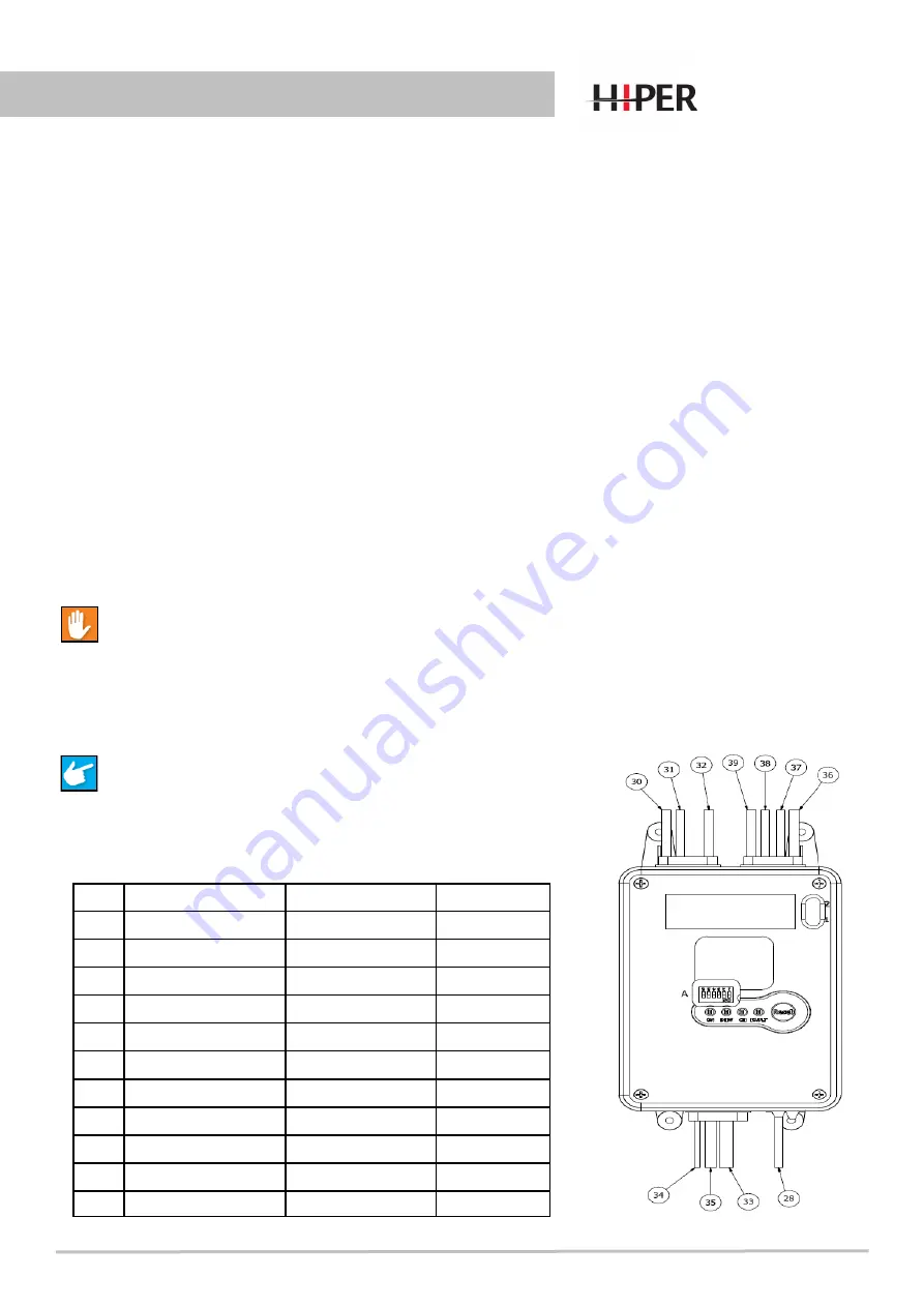
Electrical connections
All wiring to the unit must be in accordance with the IEE
regulations, and any local regulations which apply.
Note: If in any doubt a qualified electrician should be consulted.
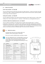
The unit is supplied with a 2m 3
-
core flying lead for connection to
mains supply. Mains connection must be done through a fused
isolator rated at 3 Amps and positioned locally to the unit.
Also provided is a 2m 2
-
core flying lead for connection to a room
thermostat.
No
Description
Individual Wiring
Connector
28
Remote Controller/
Temperature Sensor
2 Black
n/a
30
DHW Temperature Sensor
2 White
Black Connector
31
DHW Flow Sensor
Red, White and Blue
White Connector
32
Mixing Valve Stepper Motor
Blue, Black, Brown and Green
White Connector
33
Mains Cable
Blue, Brown and Green/
Yellow
n/a
34
Earth Cable
Green/Yellow
Uninsulated Crimp
Ring
35
Pump
N/a
Black Connector
36
Diverter Valve Stepper Motor
Blue, Black, Brown and Green
Blue Connector
37
CH Temperature Sensor
2 Red
Black Connector
38
Solenoid Valve
2 White
2 Terminal Crimps
39
CH Safety Thermostat
2 Black
2 Terminal Crimps
-
V3 DIRECT


