© Intatec Ltd 2020
4
Installation
1. A service valve should be installed in the water supply pipe to the valve should
maintenance be required in the future.
2. Turn off the water supply using the service valve (not supplied).
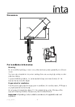
3. Screw the two threaded rods (5) and copper tail (6) into the base of the tap.
4. Install the tap (1) to the basin using sealing and metal (2 & 3) horse shoe washers and the
securing nut (4).
5. Connect the copper tail (6) to the solenoid valve (5) using the gasket (9). Ensure the flow
through the solenoid valve will be in the correct direction with flow to the tap, as marked
on the solenoid valve.
6. Connect the solenoid to the water supply using the filter washer (8). Failure to fit the filter
washer can damage the solenoid valve and invalidate the product warrantee.
6. Fix the power supply unit to the wall using the wall plugs and screws provided.
7. Connect the signal cable to the tap by assembling connector (10).
8. Turn on the water supply and check all joints for leakage.
9. Isolate via the service ball valve and tighten or remake joints if leakage occurs.
Connecting the power supply
1. Check that the sensor window is clean and that there are no obstructions in front of the
window.
2. Insert batteries into the battery box or connect the transformer to electricity supply.
3. Connect the power supply to the tap by assembling connector (11).
4. The LED under the sensor window will start flashing, when it stops the tap is ready for use.
IMPORTANT:
This product must be installed by a suitably qualified and competent person carrying the
relevant current IEE electrical qualification.
Sensor Range
The sensing range of the tap is preset and should not require adjustment.
If however the range needs to be adjusted it can be, using the following procedure;
• Unplug the power connector (10) or in the case of the transformer turn off the power
supply.
• Wait for 30 seconds before re-connecting or turning on the power supply.
• When the red LED blinks (if it switches off, it is necessary to unplug the power connector or
turn off the power supply and repeat the operation), put one hand immediately in front of
the sensor (at a maximum distance of 5cm).
• When the red LED lights up permanently, move your hand to the desired sensor distance.
• Wait for the LED to turn off before moving your hand; at this point the new distance is
stored.
• The new setting will be stored in case of battery replacement or failure of the electrical
supply.

