background image

© Intatec Ltd 2013

24

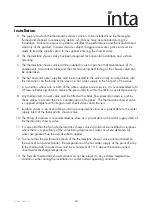
Installation

   3.  The supply to which the thermostatic shower valve is to be installed must be thoroughly 
        flushed and cleaned to remove any debris, which may have accumulated during the 
        installation. Failure to remove any debris will affect the performance and the manufacturer’s 
        warranty of the product. In areas that are subject to aggressive water, provision must be 
        made to treat the supplies prior to the supplies entering the shower valve.

   4.  The thermostatic shower valve has been designed for horizontal installation and surface 
        mounting. 

   5.  The thermostatic shower valve will be installed in such a position that maintenance of it’s 
        components, associated valves and the commissioning and testing of the shower valve can 
        be undertaken.

   6.  The hot and cold water supplies must be connected to the valve strictly in accordance with 
        the indications on the body of the valve i.e. hot water supply to the hot port of the valve.

   7.  In a situation where one or both of the water supplies are excessive, it is recommended to fit
        a Pressure Reducing Valve to reduce the pressure(s) to within the limits as quoted previously.

   8.  Any thermostatic shower valve must be fitted with a back flow prevention device, such as 
        check valves to prevent the cross contamination of supplies.  The thermostatic shower valve 
        is supplied complete with integral insert check valves and strainers.

   9.  Isolation valves in an accessible position are required as close as is practicable to the water
        supply inlets of the thermostatic shower valve.

  10. The fitting of strainers is recommended as close as is practicable to the water supply inlets of
        the thermostatic shower valve.

  11. It is essential that the fail safe thermostatic shower valve should not be installed in situations 
        where there is a possibility of the valve being deprived of water or where demands for 
        water are greater than the actual stored supplies.

  12. To ensure that the performance levels of the thermostatic shower valve are maintained (in 
        the event of cold water failure), the temperature of the hot water supply at the point of entry 
        to the thermostatic shower valve must be a minimum of 10˚C above the commissioned 
        mixed water discharge temperature.

  13. The fail-safe thermostatic shower valve must not be subject to any extreme temperature 
        variations either during the installation or under normal operating conditions.

Summary of Contents for Mio MM40014CP

Page 1: ...te as possible We cannot accept any responsibility should it be found that in any respect the information is inaccurate or incomplete or becomes so as a result of further developments or otherwise Int...

Page 2: ...Shower with overhead arm and soaker MIO12 Mio Thermostatic Concealed Shower with ceiling arm and soaker MIO13 Mio DELUXE Product Range Mio DELUXE Rinse Station with smooth hose and push button hand s...

Page 3: ...ower is pre set using ideal conditions to 38 C at the stop with a manual push button override to 46 C can be re set to suit site conditions or user preference see calibration page 13 The maximum mixed...

Page 4: ...hower Valve 1 2 3 4 6 5 Item Qty Component 1 1 Valve body and flow controller body 2 1 Flow controller 3 1 Thermostatic cartridge 4 1 Cap and check valve 5 1 Straight male x compression adaptor 6 2 An...

Page 5: ...gasket 8 1 Concealing plate 9 2 Sealing ring retainer 10 1 Temperature control concealing sleeve 11 2 Sealing ring 12 1 Temperature stop ring 13 2 Drive bush 14 2 Retaining screw 15 1 Temperature cont...

Page 6: ...ts Plaster Guard and Insulation 19 20 21 22 23 24 Item Qty Component 19 1 Preformed body insulation shell 20 2 Extension piece 21 1 Thermostatic cartridge cover 22 1 Flow controller cover 23 1 Plaster...

Page 7: ...g cold water prior to the hot water storage vessel This means that the hot and cold pressures can be significantly different Most unvented systems use an inlet manifold located directly after the pres...

Page 8: ...not available a negative head kit may be required to operate the pump Please consult the pump manufacturer s installation requirements Modulating Combi Boiler Instantaneous Gas Water Heater The drawi...

Page 9: ...ange or to the vent or a draw off pipe as close as possible to the top of the cylinder For equal tank fed pressures there is no need to fit the flow regulators This installation is the recommended min...

Page 10: ...e supply pipes can come from below above the side or through the wall The shower valve must be installed securely into the wall If not embedded into the wall with plaster the shower valve must be fixe...

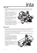
Page 11: ...s to be fitted see dimension drawing Cavity wall The shower valve must be fixed securely to the structural members of the stud wall and or an additional member may need to be included where the shower...

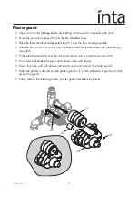
Page 12: ...er the flow control valve and secure with the retaining screw 24 Fit the plaster guard 23 over the valve and secure with two retaining screws 24 For a solid wall embed the pipes and shower valve with...

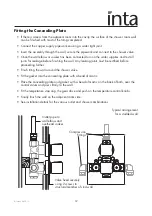
Page 13: ...eaking joints must be rectified before proceeding further Finish tiling the wall around the shower valve Fit the gasket into the concealing plate with a bead of mastic Place the concealing plate and g...

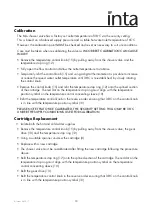
Page 14: ...stop ring must align with the temperature position symbol on the temperature control concealing sleeve 10 Refit the temperature control knob in the reverse order ensuring that 38 C on the control kno...

Page 15: ...followed by a thorough rinsing is all that is required The nozzles in the hand set should be cleaned periodically to remove any build up of debris or deposits which may affect the performance of the s...

Page 16: ...t at cold the showering temperature is too hot The hot and cold supply connections have been made in reverse Thermostatic cartridge movement limited due to lime scale build up The maximum showering te...

Page 17: ...he fitting used should not protrude beyond the surface of the ceiling Other fittings may be required to make the connection between the fitting fixed to the structural member and the water outlet Appl...

Page 18: ...30 15 120 25 5 67 5 19 1 2 4 6 3 5 9 Upper Bracket Details Lower Bracket Details 7 8 630 max Item Qty Component 1 1 Riser Rail 2 2 Wall Bracket Clip 3 2 Wall Bracket 4 4 Retaining Screw 45mm 5 2 Wall...

Page 19: ...120 25 5 67 5 19 7 8 630 max Upper Bracket Details 1 2 4 6 3 5 9 Lower Bracket Details Item Qty Component 1 1 Riser Rail 2 2 Wall Bracket Clip 3 2 Wall Bracket 4 4 Retaining Screw 45mm 5 2 Wall Bracke...

Page 20: ...age therefore should be located and directed towards a suitable bath or shower tray Take care to use power tools safely To avoid cracking ensure the wall plugs are pushed all the way behind the cerami...

Page 21: ...iser rail 1 using the 2 wall bracket screws 5 ensuring that the position of the bracket suits the centre position of the 2 wall bracket clips 2 Position the upper wall bracket onto the riser rail this...

Page 22: ...260 x 200 350 350 G B G B G B G B G B G B 15 15 15 15 20 20 170 160 Position of concealing plate adjustable MM70004CP DELUXE MM70008CP MM70003CP DELUXE MM70007CP Wall elbow part of MM70001CP rince sta...

Page 23: ...of use are appropriate for the valve Introduction The Inta range of thermostatic shower mixers have been specifically designed and manufactured to meet the requirements of BS EN 1111 1999 BS EN 1287 1...

Page 24: ...99 and also be aware of their responsibility and duty of care to ensure that all aspects of the installation comply with the regulations It has been brought to our attention that flushing water system...

Page 25: ...e s to within the limits as quoted previously 8 Any thermostatic shower valve must be fitted with a back flow prevention device such as check valves to prevent the cross contamination of supplies The...

Page 26: ...eratures are established before any attempt to commission 4 Once the supply temperatures are stable and the normal operating conditions are established the shower valve can be commissioned The followi...

Page 27: ...g performance checks shall be carried out 1 Measure the mixed water temperature at the outlet 2 Carry out the cold water supply isolation test by isolating the cold water supply wait for five seconds...

Page 28: ...n Staffordshire ST18 0PF Tel 01889 272 180 Fax 01889 272 181 email sales intatec co uk web www intatec co uk E O E 07 09 17 To activate your product warranty please visit www intatec co uk and click o...

Reviews: