IInntta
atteecc LLiim
miitteed
d,, A
Aiirrffiieelld
d IInnd
duussttrriia
all EEsstta
attee,, H
Hiixxo
onn,, S
Stta
affffss,, S
STT1
18
8 0
0PPFF
Tel: 0
01
18
88
89
9 2
20
07
72
20
00
0 Fax: 0
01
18
88
89
92
27
71
11
17
72
2 email: ssa
alleess@
@iinntta
atteecc..cco
o..uukk
© Intatec Ltd 2008
V
VRR9
99
94
4C
CPP V
Va
annd
da
all RReessiisstta
anntt S
Shho
ow
weerr H
Heea
ad
d
RReea
arr a
annd
d B
Bo
otttto
om
m C
Co
onnnneeccttiio
onnss
O
Op
peerra
attiinng
g C
Co
onnd
diittiio
onnss
Max. Operating Pressure
10 bar
Min. Operating Pressure
0.2 bar
Max. Inlet Temperature
65˚C
LLo
occa
attiio
onn
For ease of servicing always mount on a tiled wall
or similar water proof surface, never tile up to the
shower head.
Choose the position of the shower to suit the
tallest user.
The shower must not be positioned where it will
be subjected to freezing condition
C
Co
onncceea
alleed
d IInnsstta
alllla
attiio
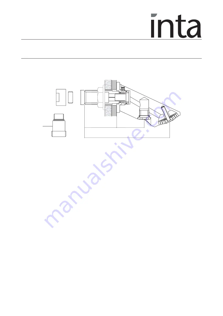
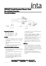
onn IInnssttrruuccttiio
onnss
The shower head is always dispatched configured
for concealed pipework.
The installation shown is typical for a tiled stud
wall.
Drill a hole through the wall 24mm in diameter.
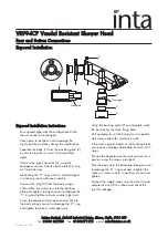
The shower head can be mounted to the wall
using a back nut (not provided) or by screws as
the exposed installation.
Using the back nut secure the shower arm to the
wall, do not over tighten
Connect the copper supply pipe to the pipe
connector using using the olive and compression
nut, tighten to make a water tight joint.
Straight or angled swivel connectors with a fibre
washer (tap connector) can also be used
Turn on the water supply and check joints for
leakage, tighten or re-make the joint until water
tight.
A
Afftteerrcca
arree
With all highly polished items, care should be
taken not to damage any of the external surfaces.
To maintain the appearance of the shower head
periodically it should be cleaned with a soft damp
cloth and a mild detergent.
The use of abrasive or solvent cleaners will
damage the finish of the product and should not
be used.
C
Co
onncceea
alleed
d IInnsstta
alllla
attiio
onn
40
mm
46.5
mm
124.4
mm
Exposed
Inlet
G
1
/
2
B


