© INTEC Video Systems, Inc.
Revision A July 2013
11
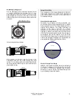
XL (Mil Spec) Alignment
The XL (Mil Spec) panel mounted connector found
on certain controllers and cameras has a 5 way
keyed alignment as shown below. This same 5 way
keyed alignment is found on the face of the inline
cable mating jack when multi-part cable extensions
are used.
Main Alignment Key
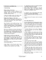
Inline cable jack shown below:
When making a connection, align the 5 keys on the
connectors and turn the outer locking ring until
locked. For XL cables with over molded back shells
the arrow with the INTEC logo is inline with the main
(top) alignment key.
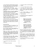
Image Orientation
The orientation of the image displayed is critical to
safe vehicle operation. An object on the right side of
your vehicle needs to be seen on the right side of
the displayed image.
Orientation Requirements
Generally if your display is facing rearwards, you
would want a Mirror image displayed from a camera
facing rearward and a True image displayed from a
camera facing forward. The image orientation of
cameras on the right or left side of a vehicle
depends on how far off of center they are facing. For
example; a camera mounted on the right side at 90º
off of the front would usually require a true image to
be displayed. But set the camera to 91º off of the
front and a mirror image may be required. Be sure to
confirm the image(s) displayed are appropriate for
your application before operating the vehicle.
How to Change Your Image
INTEC’s CVC Series cameras are set as default at
the factory to display a mirror image when used with
our CVD or CVM Series displays and monitors.
Should you need to change the default image refer
to your display’s Operation Guide.


