background image

© INTEC Video Systems, Inc.  

Revision A July 2013


4

Warnings and Cautions 


Warnings 


Do NOT attempt to connect other 
electrical devices to the power wire 
harness of the Car Vision® System 
as this can cause an over current 
situation which can lead to electrical 
shock or fire. 


If at any time you see or smell smoke 
coming from the Car Vision® 
System, stop driving, exit the vehicle 
and disconnect main power. Check 
the system and remove any 
damaged components before you 
resume normal vehicle operation. 


Do NOT attach the wiring to any 
moving parts, across sharp edges or 
close to heat sources as this may 
cause shorting of the wires and may 
lead to a fire or electrical shock. 


When installing the camera system 
be certain that all items are secure. 
Items that are not secure or mounted 
in an unstable manner can come 
loose and cause damage or personal 
injury. 


When installing the system be sure 
to use only INTEC supplied brackets. 
The Car Vision

® 

camera must be 

insulated from the vehicle body. The 
supplied camera bracket provides 
the required insulation. Failure to do 
so could result in a fire and lead to 
property damage or personal injury. 


Do NOT install the camera in any 
area that allows it to extend out past 
the vehicle as this can cause injury if 
it were to come in contact with 
people walking around the vehicle.  


Never use fuses of a larger rating 
than those supplied with your Car 
Vision® System. Use of larger rated 
fuses can cause excessive current 
through the system if a short occurs 
and could lead to a fire. 


Cautions 


Confirm that the orientation of the 
image on the display is proper. Rear 
facing cameras should yield a mirror 
image, where items on the left of the 
vehicle appear on the left side of the 
monitor. 


Before you begin driving, be sure the 
display controls are adjusted 
properly. This will avoid unnecessary 
distractions while driving. 


Do NOT attempt to open or service 
your equipment. Removal of the 
product enclosure can lead to 
electrical shock. 


You should not attempt to make any 
adjustments to the Car Vision® 
System while driving as this can lead 
to an accident. Only make 
adjustments when the vehicle is 
stopped. 


Keep the Car Vision® System clean 
and free from dirt, snow and ice. If 
the camera glass or display panel 
becomes dirty, clean them before 
use. If they are covered with snow 
and/or ice, it should be cleared off 
before use. Failure to do so could 
lead to an accident.  


When running a cable from the 
exterior to the interior of a vehicle, 
care needs to be taken to seal the 
entry point. Failure to do so could 
allow in exhaust fumes, other toxic 
gases or water. 


Summary of Contents for CVC400 Series

Page 1: ...d Operation Guide Please read this guide carefully before use and keep it for future reference Remember to complete and mail the owner registration form Installer Please give this manual to the user o...

Page 2: ...NSTALLATION INSTRUCTIONS 7 WIRING DIAGRAM 7 DISPLAY CONNECTIONS 7 DISPLAY AND CONTROLLER INSTALLATION 7 CAMERA INSTALLATION 8 CABLE INSTALLATION 9 CONNECTOR ALIGNMENT 10 HIROSE ALIGNMENT 10 MOLEX ALIG...

Page 3: ...ied and provided cables to connect the components of the system Use of other than INTEC specified and supplied components and cabling could be dangerous and result in damage to the system components a...

Page 4: ...extend out past the vehicle as this can cause injury if it were to come in contact with people walking around the vehicle Never use fuses of a larger rating than those supplied with your Car Vision S...

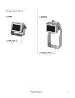
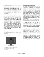
Page 5: ...INTEC Video Systems Inc Revision A July 2013 5 Package Contents Parts List CVC400 CVC400 Camera 105 00 02 004 Bracket Kit CVC400XL CVC400XL Camera 105 00 02 005 Bracket Kit...

Page 6: ...on CVC400XL Specifications Pick Up Element 1 3 CCD Pixel Count 510 H x 492 V 250 920 total pixels Lens 2 14mm f2 0 auto iris Minimum Illumination 0 5 lux 0 05 ft candles Resolution 320 lines H x 350 l...

Page 7: ...ension cable CVDR5MA Display and Controller Installation The display should be mounted where it is easily viewed and accessible to the driver but not in an area that may block or impede the drivers an...

Page 8: ...ws the system to come on automatically when the vehicle is placed in reverse Mount the remote so that it is easily accessible to the driver Please consult your INTEC Representative with any and all qu...

Page 9: ...be weatherproofed A simple means is to use 1 inch diameter gum interior heat shrink tubing available from INTEC to cover the whole connector assembly This will seal and protect the connector from dir...

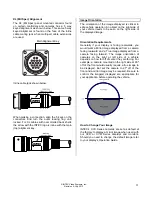
Page 10: ...ector as shown below This same mark is found on the face of the inline cable mating jack when multi part cable extensions are used Inline cable jack shown below When making a connection align the arro...

Page 11: ...ds to be seen on the right side of the displayed image Orientation Requirements Generally if your display is facing rearwards you would want a Mirror image displayed from a camera facing rearward and...

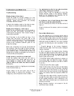
Page 12: ...ter correcting it my image is reversed After a short it may be necessary to reset the display software Refer to the displays Software Guide on the Installation and Operation CD for instructions on res...

Page 13: ...the in field adjustments and may offer alternative solutions for you to try If these solutions don t work you may be asked to send some or all of your system to INTEC A Return Materials Authorization...

Page 14: ...EC DELIVERY PREPAID AND INSURED IN ACCORDANCE WITH THE INSTRUCTIONS SET FORTH IN THE SERVICE INFORMATION SECTION OF THIS GUIDE THERE SHALL BE NO OTHER WARRANTIES EXPRESSED OR IMPLIED INCLUDING ANY IMP...

Page 15: ...__ How did you hear about the INTEC Car Vision System INTEC _____ Distributor Dealer _____ Trade Show _____ Magazine Ad _____ Article ______ Other equipment user _____ Friend _____ Previous experience...

Reviews: