background image


Instruction Manual

 | 

9


T:  303-833-6644 

or

 800-666-1611 

www.inteccorp.com 

Original Language - English 

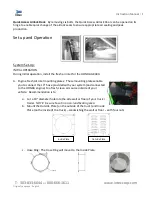
System Operation: 


1.


Energize System  

a.


Pull EMERGENCY STOP out (i.e. into the ON position). 

b.


Start HONDA engine  

i.


Turn fuel valve in the ON position. 

ii.


Place choke in the ON position if 
engine has not been running. 

iii.


Turn key to START position and 
release once engine starts. 

iv.


Reduce choke when engine is 
warming up until choke is in the OFF 
position. 

v.


Move engine throttle to FULL 
position. 

NOTE:  ENGINE HAS TO BE RUNNING AT FULL THROTTLE 
FOR GENERATOR, BLOWERS, & FORCE 5150 ELECTRICAL 
SYSTEM TO FUNCTION APPROPRIATELY. 

2.


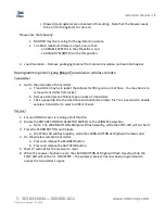
Rotate the ROTARY CONTROL SELECTOR 
SWITCH to the desired method to operate 
system. 

a.


WIRELESS REMOTE 

i.


Operate system thru Intec’s 
Long Range Transmission 
wireless remote. 

b.


WIRED REMOTE 

i.


Operate system thru 
wireless remote with Intec’s 
exclusive long lasting 
urethance jacked controls. 

ii.


Plug wired remote into the 
REMOTE QUICK 
DISCONNECT female connector.   

Note:  Unplug the wired remote when not using the wire remote to operate the FORCE 5150.  When 
unplugging, pull the metal tab back and turn ¼ turn, then remove male end from the REMOTE QUICK 
DISCONNECT female connector. 

c.


OFF 

d.


BLOWER 

i.


Operate system thru its control panel.  Blower(s) are activated in this setting. 

e.


BLOWER & AGITATOR 

airfilter 

CHOKE ON 
 

FUEL ON 
 

THROTTLE 
 

Summary of Contents for FORCE 5150

Page 1: ...tion Manual Insulation blowing machine Original Language English Intec 4040 Kodiak Court Frederick CO 80504 USA T 303 833 6644 Web www inteccorp com Email info inteccorp com T 800 666 1611 Rev Date 20...

Page 2: ...rs to truck mount units with increased production rates and installation versatility all of our durable systems are made to maximize your profit generating potential VORTEC VACUUMS Powered by Gas or E...

Page 3: ...e of Contents INTRODUCTION 1 SYMBOLS 3 SAFETY FIRST 3 HOW THE SYSTEM WORKS 4 System Set Up 7 System Operation 9 Reprogramming Intec s Long Range Transmission wireless remote 10 MAINTENANCE 11 TROUBLES...

Page 4: ...hanical issues or if machine is vibrating extensively additional damage can potential safety issues can occur Never operate equipment while standing in water as electrical shock may result Proper Prot...

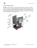
Page 5: ...in processing the insulation while moving towards the airlock column Once in the column insulation is processed additionally by the shredder bar It then moves through the slide gate and into the airl...

Page 6: ...rm acts as a shelf to support the bag of insulation being loaded into the hopper Hopper The hopper contains the insulation being fed into the agitators Engine Fresh Air Inlet Hose The Engine Fresh Air...

Page 7: ...need exists to remove foreign materials that have become entangled in the shredder bars CAUTION Always ensure machine is off and cannot be restarted when accessing the shredder box Slide Gate The sli...

Page 8: ...et for the HONDA GX390 A Engine Fresh Air Inlet mounting plates These mounting plates enable you to connect the 10 hose provided with your system and connected to the HONDA engine to a fresh clean air...

Page 9: ...fasten the open side of the Fresh Air Inlet to the 10 diameter hose Upon completion you will now have fresh clean air from outside your vehicle used to cool the HONDA engine EACH TIME YOU UTILIZE BLOW...

Page 10: ...0 ELECTRICAL SYSTEM TO FUNCTION APPROPRIATELY 2 Rotate the ROTARY CONTROL SELECTOR SWITCH to the desired method to operate system a WIRELESS REMOTE i Operate system thru Intec s Long Range Transmissio...

Page 11: ...itter from jacket b Remove small piece of black tape on back of transmitter c Stick a paperclip into the small hole and hold button down for 7 to 14 seconds to enable wireless transmitter to select a...

Page 12: ...r and exterior of the machine weekly by wiping with a rag and or blowing with compressed air this will help maintain the longevity of the mechanical components in addition to the system s finish The m...

Page 13: ...ed to visually inspected seals each week to ensure proper running condition Replace airlock seals if a cut or tear is evident Airlock seals should be replaced every 300 hours of operation or once per...

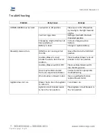
Page 14: ...oes not run HONDA is not running at full throttle Move throttle to the full HIGH position Auxiliary Blower s circuit breaker needs to be in the on position Place Auxiliary Blower s circuit breaker in...

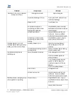
Page 15: ...stop in then remove obstruction Variable Speed is on and Variable Speed Setting is below 100 yet still a lot of air flow Auxiliary blower is on Place the Auxiliary Blower Circuit Breaker in the off po...

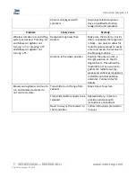
Page 16: ...open to allow for radio frequency waves to easily enter and access the receiver in the blowing machine Antenna in the down position Position the antenna into a straight position vs the 90 degree bend...

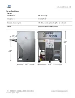
Page 17: ...4 or 800 666 1611 www inteccorp com Original Language English Specifications Weight FORCE 5150 825 lbs 375 kg Hopper size 31 cubic feet Blowers Quantity 2 115 VAC 13 4 amp two stage for each blower Mo...

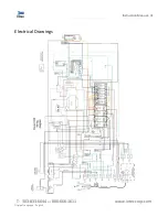
Page 18: ...Instruction Manual 19 T 303 833 6644 or 800 666 1611 www inteccorp com Original Language English Electrical Drawings...

Page 19: ...ility It is the responsibility of the consignee to file a claim Proper documentation is necessary to support the claim Please inspect all items properly prior to signing for them 2 Items received not...

Page 20: ...rantied for a period of ninety 90 days from date of factory shipment c This Warranty shall not apply to any MACHINE or component part which in the opinion of the MANUFACTURER has been altered subject...

Reviews: