background image


Instruction Manual

 | 

10


T:  303-833-6644  

www.inteccorp.com 

Original Language - English 

a.


WIRELESS REMOTE 

i.


Operate system thru Intec’s Long Range Transmission wireless remote. 

b.


WIRED REMOTE 

i.


Operate system thru wireless remote with Intec’s exclusive long lasting 
urethance jacked controls. 

ii.


Plug wired remote into the REMOTE QUICK DISCONNECT female connector.   

Note:  Unplug the wired remote when not using the wire remote to operate the SupershredzECO.  When unplugging, pull the 
metal tab back and turn ¼ turn, then remove male end from the REMOTE QUICK DISCONNECT female connector. Remote 
receptacle is not locate on the panel.  

c.


OFF 

d.


BLOWER 

i.


Operate system thru its control panel.  Blower is activated in this setting. 

e.


BLOWER & AGITATOR 

i.


Blower and agitator are activated in this setting.  Note that the blower needs to 
be on for the agitator to come on. 

3.


Load Insulation -- Remove packaging material from around insulation and load into hopper. 

REPROGRAMMING INTEC’S LONG RANGE TRANSMISSION WIRELESS REMOTE 

Please visit 

www.inteccorp.com/videos 

for further instruction on re-programming your Wireless Transmitter.  

Transmitter 

1.


Get to the underside of transmitter. 

a.


Transmitter may be in jacket that allows for fitting onto arm or hose.  You may desire to 
remove transmitter from jacket. 

b.


Remove small black sticker on back of transmitter. 

c.


Stick a paperclip into the small hole and hold button down for 7 to 14 seconds to enable 
wireless transmitter to select a different channel. 

Receiver 

1.


Ensure VANGUARD motor is running at full throttle. 

2.


Rotate the ROTARY CONTROL SELECTOR SWITCH to the WIRELESS selection. 

a.


Note:  The LEARN BUTTON LED light will flash steadily, while the SYNC-LED will not be lit. 

3.


Press the LEARN BUTTON and release. 

a.


the SYNC-LED will flash rapidly, while the LEARN BUTTON LED light will remain solid. 

4.


On the wireless remote transmitter: 

a.


Press and release the BLOWER button 

b.


Press and release the AGITATOR button 

5.


Wait 17 seconds for the receiver to reset. 

6.


When the receiver has been reset, the LEARN BUTTON LED light will flash steadily, while the 
SYNC-LED will not be lit.  COMPLETE – The wireless receiver has now been programmed to 
accept the transmitter’s signal. 


Summary of Contents for FORCE 5250

Page 1: ...Instruction Manual Insulation blowing machine Original Language English Intec 9251 Bruin BLVD Frederick CO 80504 USA T 303 833 6644 Web www inteccorp com Email info inteccorp com Rev Date 2021614 ...

Page 2: ...ruck mount units with increased production rates and installation versatility all of our durable systems are made to maximize your profit generating potential VORTEC VACUUMS Powered by Gas or Electric Engineered for High Productivity and Built to Last for High Value Generation Intec s VORTEC high powered vacuums provide the highest value offered in today s marketplace With various sizes and gas or...

Page 3: ...ntents INTRODUCTION 1 SYMBOLS 3 SAFETY FIRST 3 HOW THE SYSTEM WORKS 4 SYSTEM SET UP 7 SYSTEM OPERATION 9 REPROGRAMMING INTEC S LONG RANGE TRANSMISSION WIRELESS REMOTE 10 MAINTENANCE 11 TROUBLESHOOTING 13 SPECIFICATIONS 18 ELECTRICAL DIAGRAM 19 MAKING A CLAIM FOR DAMAGE OR LOSS 21 WARRANTY 22 ...

Page 4: ...issues or if machine is vibrating extensively additional damage can potential safety issues can occur Never operate equipment while standing in water as electrical shock may result Proper Protective Equipment When working with insulation always wear a long sleeve shirt gloves and a hat Wear goggles or safety glasses for eye protection Wear a mask for respiratory protection Hearing protection is al...

Page 5: ...ted by the blower system Insulation is discharged from the airlock through the machine outlet and into the hose The insulation is further conditioned as it travels through the hose An introduction to key components of the system follows Electrical Panel The electrical panel combined with the wireless and or wired remote provides operation of the machine Loading Platform The loading platform acts a...

Page 6: ...clean air from outside the truck trailer to ensure that your VANGUARD engine is appropriately cooled The clean air from outside also prevents fibrous particles from being pulled into your engine s cooling fins Utilize Intec s Air Inlet mounting plates to attach the hose coming from machine to fresh air NOTE Never run engine w out the air inlet hose attached Doing so will draw insulation into your ...

Page 7: ... into the desired slide gate hole to ensure the gate stays in desired position during operation Airlock The airlock transfers the insulation from the agitation system into the airstream without coming into contact with the blowers Insulation is discharged from the airlock into the hose Urethane Airlock Seals Your FORCE 5250 includes Intec s proprietary urethane airlock seals for long lasting effec...

Page 8: ...e truck sandwiching the wall or floor with four nuts c Hose Ring The Hose Ring will mount to the Inside Plate Inside Plate Outside Plate The FORCE 5250 s agitation system is built strong to last Using an advanced design for rugged durability and superior product conditioning This design allows product to go through multiple stages of conditioning prior to installation Main Agitator fluted section ...

Page 9: ...esh Air Inlet to the 8 diameter hose Upon completion you will now have fresh clean air from outside your vehicle used to cool the VANGUARD engine EACH TIME YOU UTILIZE YOUR BLOWING MACHINE 1 Obtain appropriate protective equipment 2 Attach hose to machine outlet using a hose clamp 3 Open slide gate place pin in desired opening Slide gate shown in the closed position ...

Page 10: ...rt of the Fresh Air Inlet Kit Start VANGUARD engine 1 Place choke in the ON position if engine has not been running 2 Turn key to START position and release once engine starts 3 Reduce choke when engine is warming up until choke is in the OFF position 4 Move engine throttle to FULL position 2 Rotate the ROTARY CONTROL SELECTOR SWITCH to the desired method to operate system Throttle Ignition Switch...

Page 11: ...REMOTE Please visit www inteccorp com videos for further instruction on re programming your Wireless Transmitter Transmitter 1 Get to the underside of transmitter a Transmitter may be in jacket that allows for fitting onto arm or hose You may desire to remove transmitter from jacket b Remove small black sticker on back of transmitter c Stick a paperclip into the small hole and hold button down for...

Page 12: ...ur wired remote cord is in good operating condition with the black jacket not worn and no individual wires showing If an individual wire is showing or if wires were pulled from the transmitter s jacket or male plug which inserts into the control panel correct prior to use Chain Clean and lubricate the chains once per year or as needed Use a dry lubricant when lubricating the chain do not use oil a...

Page 13: ...aced every 300 hours of operation or once per year SupershredzECO Airlock shown removed from system The Airlock of your FORCE 5250 is designed for quick removal for maintenance To watch the complete video on removing and re installing your Airlock please visit our website at www inteccorp com videos Airlock Inlet Plate Airlock Seal Airlock Rotor Plate Stainless Steel Inserts Airlock Outlet Plate 3...

Page 14: ...belts loose or missing Replace belts Blower air inlet port obstructed Clear obstruction Main Circuit Breaker tripped Reset Circuit Breaker Agitator does not run Blower has to be on for agitator to come on Turn blower on Main Circuit Breaker tripped Reset Circuit Breaker Machine is on yet no material comes out of hose Slide gate is closed Open slide gate Insulation blockage in hose Turn system off ...

Page 15: ...ff Reception range less than desired Make sure the trailer or truck s doors especially the large door in back are open to allow for radio frequency waves to easily enter and access the receiver in the blowing machine Antenna in the down position Position the antenna into a straight position vs the 90 degree bend This allows the machine to act as a source to gather the radio frequency waves and enh...

Page 16: ...l 18 T 303 833 6644 www inteccorp com Original Language English SPECIFICATIONS Weight FORCE 5250 1015 lbs 461 kg Hopper size 45 cubic feet Blower Quantity 1 Positive Displacement Motor VANGUARD 18hp with electric start ...

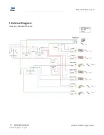
Page 17: ...Instruction Manual 19 T 303 833 6644 www inteccorp com Original Language English Electrical Diagram Force 5250 Standard Wired 2020 ...

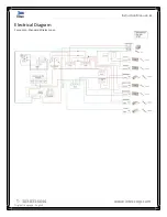
Page 18: ...Instruction Manual 20 T 303 833 6644 www inteccorp com Original Language English Electrical Diagram Force 5250 Standard Wireless 2020 ...

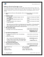
Page 19: ...ility It is the responsibility of the consignee to file a claim Proper documentation is necessary to support the claim Please inspect all items properly prior to signing for them 2 Items received not correct A Incorrect items received Contact Intec Customer Service B Incomplete order received not backordered Contact Intec Customer Service 303 833 6644 ext 102 info inteccorp com 3 Issue within the ...

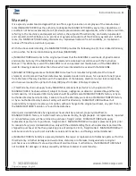
Page 20: ... for a period of ninety 90 days from date of factory shipment c This Warranty shall not apply to any MACHINE or component part which in the opinion of the MANUFACTURER has been altered subject to misuse negligence accident or operated beyond factory rated capacity All requested Warranty work should be performed at MANUFACTURER s factory or by an Authorized Factory Service Facility Failure to have ...

Reviews: