


Customer Services (858) 578-7887 & (888) GO IN
TEC
IN
TEC
Controls, 12700 Stowe Dr., Suite 1
0
0, Poway, CA 92064
Fax (858) 578-4633 & (888) FX IN
TEC
www.inteccontrols.com
Specification subject to change without notice.
Printed in USA 131119
November 19, 2013 –
Revision
Polygard® is a registered trademark of MSR
MGC2-12
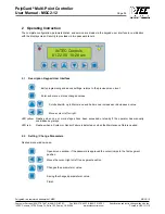
PolyGard
Controller MGC2-12
Multi-Point Controller
Serial Number – S00
User Manual
October 7, 2011


