background image

Customer Services (858) 578-7887 & (888) GO IN

TEC

IN

TEC

 Controls, 12700 Stowe Dr., Suite 1

0

0, Poway, CA 92064

Fax (858) 578-4633 & (888) FX IN

TEC

www.inteccontrols.com

Specification subject to change without notice.

Printed in USA 131119

November 19, 2013 – 

Revision

Polygard® is a registered trademark of MSR

LGC/LG2-04

PolyGard

Controller LGC/LG2-04 

Multi-Point Controller 

Serial Number – S00

User Manual 

August 11, 2006 

Specifications subject to change without notice. | USA 131119 | Page 1 of 30

12700 Stowe Drive, Suite 100, Poway, CA 92064 | Ph: (858) 578.7887 & (888) GO.IN

TEC

 | relevantsolutions.com/inteccontrols

LGC-LG2 – UserManual

Polygard® is a registered trademark of MSR | LGC/LG2-04

12700 Stowe Drive, Suite 100, Poway, CA 92064 | Ph: (858) 578.7887 & (888) GO.IN

TEC

 | relevantsolutions.com/inteccontrols

PolyGard

®

 is a registered trademark of MSR-Electronic GmbH | LGC/LG2-04

January 04, 2016 – 

Revision

February 11, 2020 – 

Revision

INTEC Controls | 12700 Stowe Drive, Suite 100, Poway, CA 92064 | Ph: (858) 578.7887 & (888) GO.INTEC | inteccontrols.com

Summary of Contents for PolyGard LGC/LG2-04

Page 1: ...1 2006 Specifications subject to change without notice USA 131119 Page 1 of 30 12700 Stowe Drive Suite 100 Poway CA 92064 Ph 858 578 7887 888 GO INTEC relevantsolutions com inteccontrols LGC LG2 UserM...

Page 2: ...point Hysteresis 16 3 6 6 Delay time ON or OFF 16 3 6 7 Control Mode 16 3 6 8 Assigned SP Fault to Relay 16 3 6 9 Assigned Stage to Relay 17 3 6 10 Assigned SP Signal to analog Output 17 3 7 Menu Syst...

Page 3: ...Notes and General Information 30 8 1 Intended product application 30 8 2 Installers responsibilities 30 8 3 Maintenance 30 8 4 Limited warranty 30 Specifications subject to change without notice USA 1...

Page 4: ...to any compatible electronic analog control DDC PLC control or automation system The adjustable parameters and staged thresholds make this system very flexible for sensor measuring and control The co...

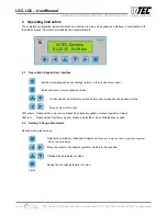
Page 5: ...r Failure is detected or when Maintenance needed 2 2 Setting Change Parameters Desired menu window open Opens menu window if password approved the cursor jumps on the first position segment which can...

Page 6: ...rvice technician A third code level permits activation or deactivation of sensor points SP A password must be re entered if 15 minutes goes by without the press of a push button All menu windows can b...

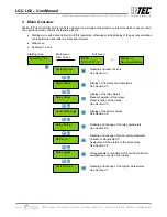
Page 7: ...ay Status Display of the sensor values See Section 3 4 Sensor Readings Reading and change of the relay parameters See Section 3 5 Relay Setup Reading and change of sensor point parameters Activate or...

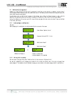
Page 8: ...le after the removal of the cause Select Menu System Errors Example Failure SP 01 3 mA Malfunction Reset Malfunction Reset or Malfunction Ereased Cause not eliminated Acknowledgement not possible 3 1...

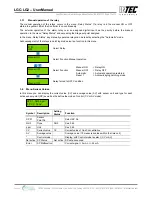
Page 9: ...in the sequence they happen The sensor points are over laid where a stage has been exceeded Changes are not possible in this menu Symbol Description Function SP 01 Sensor Point SP Point No SX Stage S...

Page 10: ...s In this menu you can display the current value CV and average value AV with sensor unit and type for each active sensor point SP as well as the define the mode of control CV or AV mode Symbol Descri...

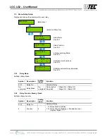
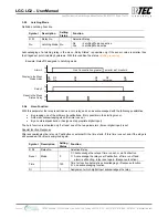
Page 11: ...Definition Relay Function Symbol Description Setting Status Function R 01 Relay No Selection Relay 0 Function 0 0 Relay Function steady 0 Relay Function flashing Periods time sec Impulse Break 1 1 Rel...

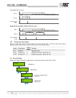
Page 12: ...nment appropriate digital input The horn function is activated only if at least one of the two parameters time or digital input is set Special function Response After acknowledging the relay via Pushb...

Page 13: ...R 01 Relay No Selection Relay DI ON External On 0 If digital input closed relay switch ON DI OFF External Off 0 If digital input closed relay switch OFF 3 6 Menu SP Setup Display and Change Parameters...

Page 14: ...3 6 9 and 3 6 10 Measuring range 300 ppm SP Signal linear Threshold 1 100 ppm Threshold 2 100 ppm Threshold 3 200 ppm Threshold 4 200 ppm Threshold 5 300 ppm Hysteresis 15 ppm Delay ON time 0 s Delay...

Page 15: ...ee the sensor manufacturing specifications The measuring range must agree with the signal 4 to 20 mA attached transmitters 4 mA Display 0 20 mA Display Measuring range max point 3 6 4 SP Signal Gas tr...

Page 16: ...mbol Description Default Status Function SP 01 Sensor Point Selection SP No 0 s Delay Time ON 0 Concentration Stage Threshold Relay is only activated at expiration of the defined time sec 0 sec No Del...

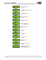
Page 17: ...al defined in the control mode current or average value is transmitted The assignment occurs in the menu assignment alarm alarm relay in the right place Analog output see also 3 7 2 3 7 Menu System Se...

Page 18: ...ime 30 s EP Module 1 Not active EP Module 2 Not active EP Module 3 Not active EP Module 4 Not active EP Module 5 Not active Time hh mm ss Specifications subject to change without notice USA 131119 Pag...

Page 19: ...J Input date for next maintenance 0853 Phone No Input the individual service phone No 3 7 4 Average Function The Controller calculates for each active sensing point the arithmetic average value from 1...

Page 20: ...Description Default Status Function Max Select Output mode Max Min Spends the minimum value of all assigned SP Max Spends the maximum value of all assigned SP Average Spends the average value of all...

Page 21: ...door Consider any unusual condition or requirements of the Customer 4 1 Electrical Connection Installation must be per local electrical codes with the consideration of the technical requirements of t...

Page 22: ...onic GmbH LGC LG2 04 Specifications subject to change without notice USA 140924 Page 5 of 6 INTEC Controls 12700 Stowe Drive Suite 100 Poway CA 92064 Ph 858 578 7887 888 GO INTEC inteccontrols com FIE...

Page 23: ...ate DC power supply ill 6 see previous page ill 4 Digital Inputs DI01 to DI04 X11 1 2 3 4 5 6 7 8 9 10 11 12 ill 5 Analog Outputs AO01 to AO02 X11 1 2 3 4 5 6 7 8 9 10 11 12 4 20 mA AO02 Com 4 20 mA A...

Page 24: ...gnment of the relays to the individual stages must occur with start up unless arrangements have been made with the factory for programming All other parameters are to be examined and adapted to the lo...

Page 25: ...P Signal Stage Setpoint 1 Stage Setpoint 2 Stage Setpoint 3 Stage Setpoint 4 Stage Setpoint 5 Hysteresis Delay ON time Delay OFF time C A Mode Assigned Failure Stage Assigned Stage Relay System Setup...

Page 26: ...Default Energezid 0 s No 0 0 0 0 0 R01 R02 R03 R04 R05 6 3 Sensor Setup Stage Setpoints Hyst Delay time sec CV AV SP No SP Status Type Measur ing range SP Signal S1 S2 S3 S4 S5 ON OFF Default Not act...

Page 27: ...wards communication to BAS Liquid Crystal Display LCD NEMA 4X controller enclosure Easy maintenance ORDERING INFORMATION Upwards Communication Options BACnet NRTL Performance Tested Certified Conforms...

Page 28: ...ity intermitted 0 to 99 RH non condensing working pressure Atmospheric 10 SPECIFICATIONS Electric Power supply controller 24 VDC 15 20 50 60 Hz auto resettable fuse sensor s transmitter s 24 VDC from...

Page 29: ...ay protection NEMA 4X IP65 installation Wall surface mounted or single gang electrical box Dimensions H x W x D 5 12 x 3 31 x 2 95 in 130 x 84 x 75 mm Cable entry 1 hole for 1 2 in conduit for wall su...

Page 30: ...ons as provided in the user manual 8 3 Maintenance It is recommended that the PolyGard LGC LG2 04 performance check is done on a routine schedule Any performance deviations may be serviced based on ne...

Reviews: