USER MANUAL - OPTIMA RT10 6K/10K-UL
VER.2106.21-One (ENG)
8
EN-IEC 62040-1: EXTERNAL BACKFEED PROTECTION
In case backfeed protection is required, an automatic external protection circuitry must be installed to provide this kind of protection to
comply with EN-IEC 62040-1. This external protection device is not included with this product. External backfeed device must be rated to
drive maximum UPS current.
Backfeed protection system must be automatic and must assure to avoid internal voltage of the UPS can feed input AC lines under battery
mode. Under normal conditions, UPS internal design avoids this kind of situations happens. However, a failure in the UPS internal Bypass
Switch could allow output voltage of the UPS inverter could be driven to the AC input lines through internal bypass lines. In battery mode,
an operator working on input AC terminals does not expect to find voltage in input lines of the UPS so that a backfeed failure could represent
an electrical shock risk for the operator.
An effective backfeed design must be able to open automatically all UPS AC input lines when AC main is power-off.
*** External Backfeed protection device is not included with this product.
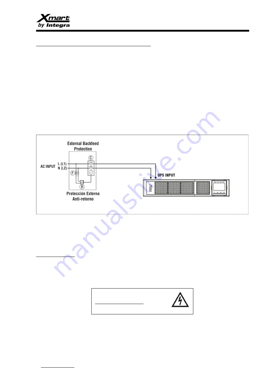
In below figure a typical automatic backfeed protection design is described.
C:
2 Poles Contactor. Normally Open. Coil voltage same tan UPS input AC voltage. Max. current similar to max. UPS input current.
R:
AC Relay. Normally Open.
F:
General purpose AC fuses. Operating voltage similar to UPS input AC voltage.
WARNING LABEL:
We strongly recommend to place warning labels in all electrical boards related to UPS circuit lines to indicate an UPS is connected to the
board. This is because a dangerous voltage could be feed by the UPS on the electrical board even AC main service is out of order.
Label design should include following information:
VOLTAGE BACKFEED RISK
UPS CONNECTED TO THIS CIRCUIT
Before working on this circuit:
* Isolate UPS
* Check for dangerous voltage in all circuit terminals.


