Power Management
46
Datasheet, Volume 1
4.1.3
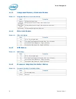
Integrated Memory Controller States
4.1.4
PCIe Link States
4.1.5
DMI States
4.1.6
Processor Graphics Controller States
Table 4-3.
Integrated Memory Controller States
State
Description
Power up
CKE asserted. Active mode.
Pre-charge
Power-down
CKE de-asserted (not self-refresh) with all banks closed.
Active Power-
Down
CKE de-asserted (not self-refresh) with minimum one bank active.
Self-Refresh
CKE de-asserted using device self-refresh.
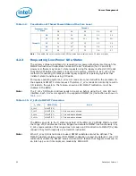
Table 4-4.
PCIe Link States
State
Description
L0
Full on – Active transfer state.
L0s
First Active Power Management low power state – Low exit latency.
L1
Lowest Active Power Management – Longer exit latency.
L3
Lowest power state (power-off) – Longest exit latency.
Table 4-5.
DMI States
State
Description
L0
Full on – Active transfer state.
L0s
First Active Power Management low power state – Low exit latency.
L1
Lowest Active Power Management – Longer exit latency.
L3
Lowest power state (power-off) – Longest exit latency.
Table 4-6.
Processor Graphics Controller States
State
Description
D0
Full on, display active.
D3 Cold
Power-off.

