Datasheet, Volume 1
103
Electrical Specifications
Notes:
1.
VAUX-DIFFp-p = 2*|VAUXP – VAUXM|. Refer to the VESA DisplayPort Standard specification for more
details.
2.
COMP resistance must be provided on the system board with 1% resistors. COMP resistors are to V
SS
.
3.
eDP_ICOMPO, eDP_ICOMPI, eDP_RCOMPO are the same resistor.
7.10
Platform Environmental Control Interface (PECI)
DC Specifications
PECI is an Intel proprietary interface that provides a communication channel between
Intel processors and chipset components to external Adaptive Thermal Monitor devices.
The processor contains a Digital Thermal Sensor (DTS) that reports a relative die
temperature as an offset from Thermal Control Circuit (TCC) activation temperature.
Temperature sensors located throughout the die are implemented as analog-to-digital
converters calibrated at the factory. PECI provides an interface for external devices to
read the DTS temperature for thermal management and fan speed control. More
detailed information may be found in the
Platform Environment Control Interface
(PECI) Specification
.
7.10.1
PECI Bus Architecture
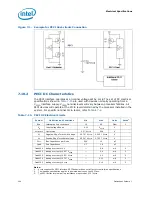
The PECI architecture based on
wired OR bus
that the clients (as 2nd Generation
Intel
®
Core™ processor family mobile PECI) can pull up high (with strong drive).
The idle state on the bus is near zero.
demonstrates PECI design and connectivity, while the host/originator can be
3rd party PECI host, and one of the PECI client is a 2nd Generation Intel
®
Core™
processor family mobile PECI device.
Table 7-14. eDP DC Specifications
Symbol
Parameter
Min
Typ
Max
Units
Notes
eDP_HPD#
V
IL
Input Low Voltage
-0.1
—
0.3 * V
CCIO
V
V
IH
Input High Voltage
0.7 * V
CCIO
—
V
CCIO
V
eDP_AUX, eDP_AUX#
V
AUX-DIFFp-p
(Tx) AUX Peak-to-Peak Voltage at the
transmitting device
0.4
—
0.6
1
V
AUX-DIFFp-p
(Rx) AUX Peak-to-Peak Voltage at the
receiving device
0.32
—
1.36
V
1
eDP COMPs
eDP_ICOMPI
Comp Resistance
24.75
25
25.25
2, 3
eDP_COMPIO
Comp Resistance
24.75
25
25.25
2, 3


