Signal Description
82
Datasheet, Volume 1
6.8
PLL Signals
6.9
TAP Signals
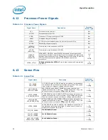
Table 6-10. PLL Signals
Signal Name
Description
Direction/
Buffer Type
BCLK
BCLK#
Differential bus clock input to the processor
I
Diff Clk
DPLL_REF_CLK
DPLL_REF_CLK#
Embedded Display Port PLL Differential Clock In: 120 MHz.
I
Diff Clk
Table 6-11. TAP Signals
Signal Name
Description
Direction/
Buffer Type
BPM#[7:0]
Breakpoint and Performance Monitor Signals:
These signals are
outputs from the processor that indicate the status of breakpoints
and programmable counters used for monitoring processor
performance.
I/O
CMOS
BCLK_ITP
BCLK_ITP#
These pins are connected in parallel to the top side debug probe to
enable debug capacities.
I
DBR#
DBR# is used only in systems where no debug port is implemented
on the system board. DBR# is used by a debug port interposer so
that an in-target probe can drive system reset.
O
PRDY#
PRDY# is a processor output used by debug tools to determine
processor debug readiness.
O
Asynchronous
CMOS
PREQ#
PREQ# is used by debug tools to request debug operation of the
processor.
I
Asynchronous
CMOS
TCK
TCK (Test Clock):
This signal provides the clock input for the
processor Test Bus (also known as the Test Access Port). TCK must be
driven low or allowed to float during power on Reset.
I
CMOS
TDI
TDI (Test Data In):
This signal transfers serial test data into the
processor. TDI provides the serial input needed for JTAG specification
support.
I
CMOS
TDO
TDO (Test Data Out):
This signal transfers serial test data out of the
processor. TDO provides the serial output needed for JTAG
specification support.
O
Open Drain
TMS
TMS (Test Mode Select):
A JTAG specification support signal used by
debug tools.
I
CMOS
TRST#
T
RST# (Test Reset):
This signal resets the Test Access Port (TAP)
logic. TRST# must be driven low during power on Reset.
I
CMOS

