Intel® Thermal/Mechanical Reference Design Information
R
Thermal/Mechanical Design Guide
49
5.7.2
Mechanical Interface to the Reference Attach Mechanism
The attach mechanism component from the Intel RCBFH-3 Reference Design can be used by
other 3
rd
party cooling solutions. The attach mechanism consists of:
•
A metal attach clip that interfaces with the heatsink core, see Appendix G, Figure 48, and
Figure 49 for the component drawings.
•
Four plastic fasteners, see Appendix G, Figure 50, Figure 51, Figure 52, and Figure 53 for
the component drawings.
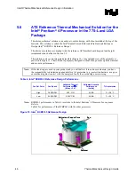
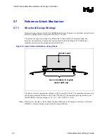
Figure 10 and Figure 11 show the reference attach mechanism as part of the Intel RCBFH-3
Reference Design. The clip is assembled to heatsink during copper core insertion, and is meant to
be trapped between the core shoulder and the extrusion as shown in Figure 13. Figure 54 in
Appendix G provides additional details.
Figure 13. Reference Clip/Heatsink Assembly
Core shoulder
traps clip in place
Core shoulder
traps clip in place
Clip
Summary of Contents for 640 - Pentium 4 640 3.2GHz 800MHz 2MB Socket 775 CPU
Page 14: ...Introduction R 14 Thermal Mechanical Design Guide ...
Page 38: ...Thermal Management Logic and Thermal Monitor Feature R 38 Thermal Mechanical Design Guide ...
Page 52: ...Intel Thermal Mechanical Reference Design Information R 52 Thermal Mechanical Design Guide ...
Page 60: ...Acoustic Fan Speed Control R 60 Thermal Mechanical Design Guide ...
Page 72: ...Heatsink Clip Load Metrology R 72 Thermal Mechanical Design Guide ...
Page 99: ...Mechanical Drawings R Thermal Mechanical Design Guide 99 Figure 50 Reference Fastener Sheet 1 ...
Page 103: ...Mechanical Drawings R Thermal Mechanical Design Guide 103 Figure 54 Clip Heatsink Assembly ...


