Getting Started
Intel
®
Atom™ Processor E660 with Intel
®
Platform Controller Hub EG20T Development Kit
User Manual
January 2012
20
Document Number: 324213-002
2.5.7
SATA Connectors
The carrier board provides two SATA connectors. These connectors (X29, X30) are
connected to the Intel
®
PCH EG20T for SATA Gen 1 or Gen2 compliance devices.
There is one peripheral power connector (X48) provided for the purpose of powering
external devices such as a SATA drive.
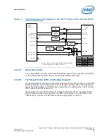
Figure 4
describes the carrier board SATA interface connection.
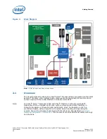
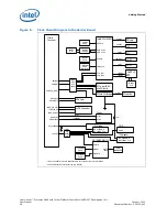
Figure 3.
PCI Express* Block Diagram of the Carrier Board
SMB_Bus
Intel® PCH
EG20T
PCIe*
Signal Switch
miniPCIe*
slot (X8)
PCIe* Lane0
PCIe* Lane3
PCIe* slot #3
(X10)
PCIe* slot #2
(X52)
PCI slot #4
(X12)
PCIe* to PCI
Bridge IC
PCIe* Lane3(*1)
PCIe* Lane3(*1)
PCIe* Lane2
PCIe* Lane1
(*1): The PCIe* lane can be alternately used by the signal switch selection .
DipSW
SW4-bit1
COMe*
Connector

