Reference Board Summary
Intel
®
Atom™ Processor E660 with Intel
®
Platform Controller Hub EG20T Development Kit
User Manual
January 2012
42
Document Number: 324213-002
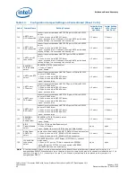
J13
UART0 port
DCD connection
connection select between UART0 DSR port of IOH to RS232C
driver
1-2 short: connect to RS232C driver
open: no connection (if the case of using UART0 port in baud
rate up 4Mbps, it is necessary to be set open.)
1-2 short
1-2 short
J14
UART0 port
DSR connection
connection select between UART0 DSR port of IOH to RS232C
driver
1-2 short: connect to RS232C driver
open: no connection (if the case of using UART0 port in baud
rate up 4Mbps, it is necessary to be set open.)
1-2 short
1-2 short
J15
UART0 port RI
connection
connection select between UART0 RI port of IOH to RS232C
driver
1-2 short: connect to RS232C driver
open: no connection (if the case of using UART0 port in baud
rate up 4Mbps, it is necessary to be set open.)
1-2 short
1-2 short
J16
RS485DRV
TX/RX Enable
select
RS485DRV (TX/RX) enable select
1-2 short: Disable
open: Enable
1-2 short
1-2 short
J17
UART0 port RTS
select
connection select between UART0 RTS port of IOH to RS232C
driver or RS485 driver
1-2 short: connect to RS232C driver
2-3 short: connect to RS485 driver
open: no connection
1-2 short
1-2 short
J18
UART0 port
CTS select
connection select between UART0 CTS port of IOH to RS232C
driver or RS485 driver
1-2 short: connect to RS232C driver
2-3 short: connect to RS485 driver
open: no connection
1-2 short
1-2 short
J19
UART0 port
TXD select
connection select between UART0 TXD port of IOH to RS232C
driver or RS485 driver
1-2 short: connect to RS232C driver
2-3 short: connect to RS485 driver
open: no connection
1-2 short
1-2 short
J20
UART0 port
RXD select
connection select between UART0 RXD port of IOH to RS232C
driver or RS485 driver
1-2 short: connect to RS232C driver
2-3 short: connect to RS485 driver
open: no connection
1-2 short
1-2 short
J21
RS485DRV
CTS/RTS
Enable select
RS485DRV (CTS/RTS) enable select
1-2 short: Disable
open: Enable
1-2 short
1-2 short
J22
BIOS
Disable/Enable
select
BIOS on COMe module Enable select
1-2 short: Disable
open: Enable (this case of BIOS using on COMe Module)
open
open
J23
Audio Codec
SDATA IN
select
Audio codec (Realtek ALC888-GR) "SDATA-IN" connection select
1-2 short: connect to AC_SDIN2 of COMe connector
3-4 short: connect to AC_SDIN0 of COMe connector
3-4 short
3-4 short
J24
I2C-EEPROM
connection
select
I2C-EEPROM of PCIe to PCI Bridge IC(PI7C9X111) connect
mode select
1-2 short: I2C port on COMe is connected to EEPROM
open: I2C port on PI7C9X111 is connected to EEPROM
(This EEPROM is no use by default.)
open
open
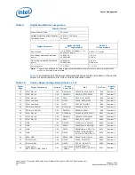
Table 13.
Configuration Jumper Settings on Carrier Board (Sheet 2 of 3)
Label
Jumper Name
Setting Context
Initial Setting
(AC Adapter
Use Case)
Initial Setting
(ATX-Power
Use Case)
Note:
A jumper consists of two or more pins mounted on the board. When a jumper cap is placed over two pins, it is
designated as SHORT. When there are more than two pins on the jumper, the pins to be shorted are indicated as 1–2 (to
short pin 1 to pin 2), 2–3 (to short pin 2 to pin 3), etc. When no jumper cap is to be placed on the jumper, it is
designated as OPEN.

