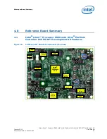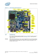
Reference Board Summary
Intel
®
Atom™ Processor E660 with Intel
®
Platform Controller Hub EG20T Development Kit
User Manual
January 2012
48
Document Number: 324213-002
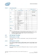
Notes:
1.
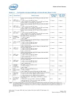
D3-D1 are power status indicator; if the power status is S5, then D1 LED is on; if the power status is
S3, then D1 and D2 LED are on; if the power status is S0, then D1 to D3 LED are on.
2.
HDD LED of the front panel is status indication of HDD access. These signals are controlled from SIO.
3.
LAN ACT(D13), LINK(D14) LEDs are indicated by the build-in LED in the LAN connector.
4.
X44 other pins assigned are omitted.
4.6
PCI Express* Routing
4.6.1
PCI Express* x1 Port0
This is the first PCIe* port from the COM Express* module. It connects to the Intel
®
PCH EG20T.
4.6.2
PCI Express* x1 Port1
This is the second PCIe* port from the COM Express* module. The PCI Express* port 1
link connects to a PCIe*-PCI bridge (Pericom PI7C9X111SL*) which provides one PCI
slot (X12).
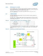
4.6.3
PCI Express* x1 Port2
This is the third PCIe* port from the COM Express* module. It connects to a x4 PCIe*
slot (X52).
Table 17.
Carrier Board LEDs
Target
LED
FP-Header (X44)(*4)
Silk
Status Indication
Color
No.
Status Indication
Power
D1
S5 Indication(*1)
red
2
S0 Indication
(LED_GRN)
D2
S3 Indication(*1)
yellow
4
-
D3
S0 Indication(*1)
green
-
-
HDD
D4
COMe_HDD
green
3
COMe_HDD/
SATA0/SATA1(*2)
D5
SATA0
green
3
-
D6
SATA1
green
-
-
SDIO
D7
SDIO0
green
-
-
D8
SDIO1
green
-
-
POST Code
D9
POST Code Port80h
(HIGHNIBBLE) (7
segments)
red
-
-
D10
POST Code Port80h (LOW
NIBBLE) (7 segments)
red
-
-
LAN Port(*3)
D11
LED0 (ACT)
yellow
-
-
D12
LED1 (LINK)
green
-
-
D13
LED2
green
-
-
PCIe*
miniCard
D14
WWAN
green
-
-
D15
WLAN
green
-
-
D16
WPAN
green
-
-


