background image

Technical Reference 

 39 

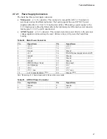
2.3  Fixed I/O Map 

Table 11.  I/O Map 

Address (hex) 

Size 

Description 

0000 - 00FF 

256 bytes 

Used by the Desktop Board D102GGC2.  Refer to the 
IXP 450 data sheet for dynamic addressing information. 

0170 - 0177 

8 bytes 

Secondary Parallel ATA IDE channel command block 

01F0 - 01F7 

8 bytes 

Primary Parallel ATA IDE channel command block 

0228 - 022F 

(Note 1)

 8 

bytes 

LPT3 

0278 - 027F 

(Note 1)

 8 

bytes 

LPT2 

02E8 - 02EF 

(Note 1)

 8 

bytes 

COM4 

02F8 - 02FF 

(Note 1)

 8 

bytes 

COM2 

0374 - 0377 

4 bytes 

Secondary Parallel ATA IDE channel control block 

0377, bits 6:0 

7 bits 

Secondary IDE channel status port 

0378 - 037F 

8 bytes 

LPT1 

03E8 - 03EF 

8 bytes 

COM3 

03F0 - 03F5 

6 bytes 

Diskette channel  

03F6 – 03F7 

1 byte 

Primary Parallel ATA IDE channel control block 

03F8 - 03FF 

8 bytes 

COM1 

04D0 - 04D1 

2 bytes 

Edge/level triggered PIC 

LPTn + 400 

8 bytes 

ECP port, LPTn base a 400h 

0CF8 - 0CFB 

(Note 2)


4 bytes 

PCI Conventional bus configuration address register 

0CF9 

(Note 3)


1 byte 

Reset control register 

0CFC - 0CFF 

4 bytes 

PCI Conventional bus configuration data register 

FB00 – FB07 

8 bytes 

Primary Parallel ATA IDE bus master registers 

FB08 – FB0F 

8 bytes 

Secondary Parallel ATA IDE bus master registers 

Notes: 

1. 

Default, but can be changed to another address range 

2. 

Dword access only 

3. 

Byte access only 


NOTE 

Some additional I/O addresses are not available due to IXP 450 address aliasing.  The IXP 450 
data sheet provides more information on address aliasing. 

Summary of Contents for BLKD102GGC2

Page 1: ...ontain design defects or errors known as errata that may cause the product to deviate from published specifications Current characterized errata are documented in the Intel Desktop Board D102GGC2 Specification Update Intel Desktop Board D102GGC2 Technical Product Specification ...

Page 2: ...ing of documents and other materials and information does not provide any license express or implied by estoppel or otherwise to any such patents trademarks copyrights or other intellectual property rights Intel may make changes to specifications and product descriptions at any time without notice Designers must not rely on the absence or characteristics of any features or instructions marked rese...

Page 3: ...ion 1 A description of the hardware used on the Desktop Board D102GGC2 2 A map of the resources of the Desktop Board 3 The features supported by the BIOS Setup program 4 A description of the BIOS error messages beep codes and POST codes Typographical Conventions This section contains information about the conventions used in this specification Not all of these symbols and abbreviations appear in a...

Page 4: ...e J5J1 is a connector located at 5J It is the first connector in the 5J area GB Gigabyte 1 073 741 824 bytes GB sec Gigabytes per second KB Kilobyte 1024 bytes Kbit Kilobit 1024 bits kbits sec 1000 bits per second MB Megabyte 1 048 576 bytes MB sec Megabytes per second Mbit Megabit 1 048 576 bits Mbit sec Megabits per second xxh An address or data value ending with a lowercase h indicates a hexade...

Page 5: ...Drive Controller 25 1 7 4 Keyboard and Mouse Interface 25 1 8 High Definition Audio Subsystem 26 1 8 1 Audio Subsystem Software 26 1 8 2 Audio Connectors 27 1 9 LAN Subsystem 28 1 9 1 LAN Subsystem Software 28 1 10 Hardware Management Subsystem 29 1 10 1 Fan Monitoring 29 1 10 2 Chassis Intrusion and Detection 29 1 11 Power Management 29 1 11 1 ACPI 30 1 11 2 Hardware Support 32 2 Technical Refere...

Page 6: ...roduct Certification Markings Board Level 66 3 Overview of BIOS Features 3 1 Introduction 67 3 2 BIOS Flash Memory Organization 68 3 3 Resource Configuration 68 3 3 1 PCI Autoconfiguration 68 3 3 2 PCI IDE Support 68 3 4 System Management BIOS SMBIOS 69 3 5 Legacy USB Support 69 3 6 BIOS Updates 70 3 6 1 Language Support 70 3 6 2 Custom Splash Screen 70 3 7 Boot Options 71 3 7 1 CD ROM Boot 71 3 7...

Page 7: ...onnector LED States 28 6 Effects of Pressing the Power Switch 30 7 Power States and Targeted System Power 31 8 Wake up Devices and Events 31 9 System Memory Map 37 10 DMA Channels 38 11 I O Map 39 12 Interrupts 40 13 PCI Configuration Space Map 41 14 PCI Interrupt Routing Map 41 15 Back Panel Connectors Shown in Figure 6 43 16 Component side Connectors Shown in Figure 7 45 17 Front Panel Audio Con...

Page 8: ...ngs 64 35 EMC Regulations 65 36 Product Certification Markings 66 37 BIOS Setup Program Menu Bar 68 38 BIOS Setup Program Function Keys 68 39 Boot Device Menu Options 71 40 Supervisor and User Password Functions 73 41 Beep Codes 75 42 BIOS Error Messages 75 43 Port 80h POST Code Ranges 76 44 Port 80h POST Codes 77 45 Typical Port 80h POST Sequence 80 ...

Page 9: ...nline Support 15 1 3 Processor 15 1 4 System Memory 16 1 5 ATI Radeon Xpress 200 Chipset 17 1 6 PCI Express Connectors 24 1 7 Legacy I O Controller 24 1 8 High Definition Audio Subsystem 26 1 9 LAN Subsystem 28 1 10 Hardware Management Subsystem 29 1 11 Power Management 29 ...

Page 10: ... SMSC SCH5017 Legacy I O controller for hardware management diskette drive serial parallel and PS 2 ports USB Support for USB 2 0 devices Peripheral Interfaces Eight USB ports One serial port One parallel port Four Serial ATA interfaces Two Parallel ATA IDE interfaces with UDMA 33 ATA 66 100 support One diskette drive interface PS 2 keyboard and mouse ports LAN Support 10 100 Mbits sec LAN subsyst...

Page 11: ...marketing channels Please contact your Intel representative to determine which manufacturing options are available to you Table 2 Manufacturing Options SATA RAID Support for RAID 0 data striping and RAID 1 data mirroring on the SATA ports For information about Refer to Available configurations for the Desktop Board D102GGC2 Section 1 1 4 page 14 ...

Page 12: ...oduct Specification 12 1 1 3 Board Layout Figure 1 shows the location of the major components OM18247 A T R S D C E B H I J K L F G Y BB Z AA U V W X O N M P Q DD CC Figure 1 Board Components Table 3 lists the components identified in Figure 1 ...

Page 13: ... 2 K Processor fan connector L Chassis intrusion connector M Legacy I O controller N Main power connector O Diskette drive connector P Parallel ATE IDE connectors 2 Q Battery R Front chassis fan connector S Serial ATA connectors 4 T Auxiliary front panel power LED connector U Front panel connector V 4 Mbit Firmware Hub FWH W IXP 450 Southbridge X Speaker Y Front panel USB connector Z BIOS Setup co...

Page 14: ...rallel Port Serial Port Parallel ATA IDE Interface LPC Bus OM18294 Realtek ALC883 Audio Codec Mic In Front Panel Mic In or Center LFE Out Line Out Front Panel LAN Connector Realtek 8101L LAN Controller connector or socket PCI Bus SMBus High Definition Audio Link USB Memory Bus SMBus PCI Slot 1 PCI Slot 2 Line In or Rear Left Right Out Line Out or Front Left Right Out Serial ATA IDE Connectors 4 Se...

Page 15: ...ign motherbd 1 3 Processor The board is designed to support the following processors Intel PentiumD processor in an LGA775 processor socket with an 800 or 533 MHz system bus Intel Pentium4 processor in an LGA775 processor socket with an 800 or 533 MHz system bus Intel Celeron D processor in an LGA775 processor socket with a 533 MHz system bus For information about Refer to Supported processors for...

Page 16: ...hipset to accurately configure memory settings for optimum performance If non SPD memory is installed the BIOS will attempt to correctly configure the memory settings but performance and reliability may be impacted or the DIMMs may not function under the determined frequency Table 4 lists the supported DIMM configurations Table 4 Supported Memory Configurations DIMM Capacity Configuration SDRAM De...

Page 17: ...d graphics processor based on the ATI Radeon X300 core contained within the ATI Radeon Xpress 200 Northbridge is used or a PCI Express x16 add in card can be used 1 5 2 Firmware Hub FWH The Firmware Hub provides the nonvolatile storage of the Intel BIOS 1 5 3 USB The board supports up to eight USB 2 0 ports supports UHCI and EHCI and uses UHCI and EHCI compatible drivers The IXP 450 Southbridge pr...

Page 18: ...rotocol on IDE bus supporting host and target throttling and transfer rates of up to 66 MB sec ATA 66 protocol is similar to Ultra DMA and is device driver compatible ATA 100 DMA protocol on IDE bus allows host and target throttling The IXP 450 s ATA 100 logic can achieve read transfer rates up to 100 MB sec and write transfer rates up to 88 MB sec ATA 133 DMA protocol on IDE bus allows host and t...

Page 19: ...Many Serial ATA drives use new low voltage power connectors and require adaptors or power supplies equipped with low voltage power connectors For more information see http www serialata org For information about Refer to The location of the Serial ATA IDE connectors Figure 7 page 44 1 5 4 3 Serial ATA RAID Optional As a manufacturing option the board s Serial ATA controller supports the following ...

Page 20: ...ON Risque d explosion si la pile usagée est remplacée par une pile de type incorrect Les piles usagées doivent être recyclées dans la mesure du possible La mise au rebut des piles usagées doit respecter les réglementations locales en vigueur en matière de protection de l environnement FORHOLDSREGEL Eksplosionsfare hvis batteriet erstattes med et batteri af en forkert type Batterier bør om muligt g...

Page 21: ...baterias devem ser recicladas nos locais apropriados A eliminação de baterias usadas deve ser feita de acordo com as regulamentações ambientais da região AŚCIAROŽZNAŚĆ Існуе рызыка выбуху калі заменены акумулятар неправільнага тыпу Акумулятары павінны па магчымасці перепрацоўвацца Пазбаўляцца ад старых акумулятараў патрэбна згодна з мясцовым заканадаўствам па экалогіі UPOZORNÌNÍ V případě výměny b...

Page 22: ...entările locale privind protecţia mediului ВНИМАНИЕ При использовании батареи несоответствующего типа существует риск ее взрыва Батареи должны быть утилизированы по возможности Утилизация батарей должна проводится по правилам соответствующим местным требованиям UPOZORNENIE Ak batériu vymeníte za nesprávny typ hrozí nebezpečenstvo jej výbuchu Batérie by sa mali podľa možnosti vždy recyklovať Likvid...

Page 23: ...ОРОГА Використовуйте батареї правильного типу інакше існуватиме ризик вибуху Якщо можливо використані батареї слід утилізувати Утилізація використаних батарей має бути виконана згідно місцевих норм що регулюють охорону довкілля ...

Page 24: ...ake events from ACPI S1 S3 S4 or S5 Software compatible with the PCI Power Management Event PME mechanism defined in the PCI Power Management Specification Rev 1 1 1 7 Legacy I O Controller The SMSC SCH5017 Legacy I O controller provides the following features One serial port One parallel port with Extended Capabilities Port ECP and Enhanced Parallel Port EPP support Serial IRQ interface compatibl...

Page 25: ...etup program to configure the diskette drive interface For information about Refer to The location of the diskette drive connector Figure 7 page 44 1 7 4 Keyboard and Mouse Interface PS 2 keyboard and mouse connectors are located on the back panel NOTE The keyboard is supported in the bottom PS 2 connector and the mouse is supported in the top PS 2 connector Power to the computer should be turned ...

Page 26: ...B Microphone input supporting Stereo microphone Microphone boost INTEGRATOR S NOTE For the front panel jack sensing and automatic retasking feature to function a front panel daughter card that is designed for High Definition Audio must be used Otherwise an AC 97 style audio front panel connector will be assumed and the Line Out and Mic In functions will be permanent 1 8 1 Audio Subsystem Software ...

Page 27: ...s are shown in Figure 3 Back Panel Audio Connectors Line In or Rear Left Right Out Line Out or Front Left Right Out Mic In or Center LFE Subwoofer Out OM18246 Mic In Front Panel Audio Connectors Line Out Figure 3 Front Back Panel Audio Connector Options for High Definition Audio Subsystem For information about Refer to The location of the front panel audio connector Figure 7 page 44 The signal nam...

Page 28: ...ED Yellow LED OM15076 Figure 4 LAN Connector LED Locations Table 5 describes the LED states when the board is powered up and the 10 100 Mbits sec LAN subsystem is operating Table 5 LAN Connector LED States LED Color LED State Condition Off LAN link is not established On LAN link is established Green Blinking LAN activity is occurring Off 10 Mbits sec data rate is selected Yellow On 100 Mbits sec d...

Page 29: ...el Desktop Utilities LANDesk software or third party software For information about Refer to The functions of the fan connectors Section 1 11 2 2 page 33 1 10 2 Chassis Intrusion and Detection The board supports a chassis security feature that detects if the chassis cover is removed The security feature uses a mechanical switch on the chassis that attaches to the chassis intrusion connector When t...

Page 30: ...e Power Switch If the system is in this state and the power switch is pressed for the system enters this state Off ACPI G2 G5 Soft off Less than four seconds Power on ACPI G0 working state On ACPI G0 working state Less than four seconds Soft off Standby ACPI G1 sleeping state On ACPI G0 working state More than four seconds Fail safe power off ACPI G2 G5 Soft off Sleep ACPI G1 sleeping state Less t...

Page 31: ...er to the system No power D3 no power for wake up logic except when provided by battery or external source No power to the system Service can be performed safely Notes 1 Total system power is dependent on the system configuration including add in boards and peripherals powered by the system chassis power supply 2 Dependent on the standby power consumption of wake up devices used in the system 1 11...

Page 32: ...on the wake devices supported and manufacturing options The board provides several power management hardware features including Power connector Fan connectors LAN wake capabilities Instantly Available PC technology Resume on Ring Wake from USB Wake from PS 2 keyboard PME signal wake up support WAKE signal wake up support LAN wake capabilities and Instantly Available PC technology require power fro...

Page 33: ...controller All fan connectors support closed loop fan control that can adjust the fan speed or switch the fan on or off as needed All fan connectors have a 12 V DC connection For information about Refer to The signal names of the processor fan connector Table 20 page 46 The signal names of the chassis fan connectors Table 21 page 46 1 11 2 3 LAN Wake Capabilities CAUTION For LAN wake capabilities ...

Page 34: ...rds that also support this specification can participate in power management and can be used to wake the computer The use of Instantly Available PC technology requires operating system support and PCI 2 2 compliant add in cards PCI Express add in cards and drivers 1 11 2 5 Resume on Ring The operation of Resume on Ring can be summarized as follows Resumes operation from ACPI S1 or S3 states Detect...

Page 35: ...off Figure 5 shows the location of the standby power indicator LED CAUTION If AC power has been switched off and the standby power indicator is still lit disconnect the power cord before installing or removing any devices connected to the board Failure to do so could damage the board and any attached devices OM19010 CR1 Figure 5 Location of the Standby Power Indicator LED ...

Page 36: ...Intel Desktop Board D102GGC2 Technical Product Specification 36 ...

Page 37: ...Table 9 lists the system memory map Table 9 System Memory Map Address Range decimal Address Range hex Size Description 1024 K 4194304 K 100000 FFFFFFFF 4095 MB Extended memory 960 K 1024 K F0000 FFFFF 64 KB Runtime BIOS 896 K 960 K E8000 EFFFF 32 KB Reserved 800 K 896 K C8000 E7FFF 128 KB Potential available high DOS memory open to the PCI Conventional bus Dependent on video adapter used 640 K 800...

Page 38: ...Channels Table 10 DMA Channels DMA Channel Number Data Width System Resource 0 8 or 16 bits Open 1 8 or 16 bits Parallel port 2 8 or 16 bits Diskette drive 3 8 or 16 bits Parallel port for ECP or EPP 4 8 or 16 bits DMA controller 5 16 bits Open 6 16 bits Open 7 16 bits Open ...

Page 39: ... 03E8 03EF 8 bytes COM3 03F0 03F5 6 bytes Diskette channel 03F6 03F7 1 byte Primary Parallel ATA IDE channel control block 03F8 03FF 8 bytes COM1 04D0 04D1 2 bytes Edge level triggered PIC LPTn 400 8 bytes ECP port LPTn base address 400h 0CF8 0CFB Note 2 4 bytes PCI Conventional bus configuration address register 0CF9 Note 3 1 byte Reset control register 0CFC 0CFF 4 bytes PCI Conventional bus conf...

Page 40: ...terrupt from slave PIC 3 COM2 Note 1 4 COM1 Note 1 5 LPT2 Plug and Play option User available 6 Diskette drive 7 LPT1 Note 1 8 Real time clock 9 User available 10 User available 11 User available 12 Onboard mouse port if present else user available 13 Reserved math coprocessor 14 Primary IDE Serial ATA if present else user available 15 Secondary IDE Serial ATA if present else user available 16 Not...

Page 41: ...I PCI bridge 01 05 00 ATI VGA controller 01 Notes 1 and 3 PCI Express x16 connector 02 Notes 2 and 3 PCI Express x1 connector 02 Note 3 02 00 Ethernet controller 03 Note 3 03 00 PCI Conventional bus connector 1 03 Note 3 04 00 PCI Conventional bus connector 2 Notes 1 Present only when a PCI Express x16 graphics card is installed 2 Present only when a PCI Express x1 add in card is installed 3 Bus n...

Page 42: ...o devices inside the computer s chassis such as fans and internal peripherals Do not use these connectors to power devices external to the computer s chassis A fault in the load presented by the external devices could cause damage to the computer the power cable and the external devices themselves This section describes the board s connectors The connectors can be divided into these groups Back pa...

Page 43: ... Connectors Shown in Figure 6 Item callout from Figure 6 Description A PS 2 mouse port Green B PS 2 keyboard port Purple C Parallel port Burgundy D Serial port A Teal E VGA port F USB ports 4 G LAN H Line in or Rear Left Right Out I Line out or Front Left Right Out J Mic in or Center LFE Subwoofer Out NOTE The back panel audio line out connector is designed to power headphones or amplified speaker...

Page 44: ...hows the locations of the component side connectors OM19009 C A B S O P Q E F D H I G U V T K L J M N R 1 9 2 10 10 2 7 1 2 7 1 10 2 9 1 1 1 1 1 1 1 3 1 3 1 3 2 4 1 4 1 1 13 24 1 2 1 2 1 2 40 40 39 39 33 1 Figure 7 Component side Connectors Table 16 lists the component side connectors identified in Figure 7 ...

Page 45: ...lel ATA IDE connector M Secondary parallel ATA IDE connector N Serial ATA connector 1 O Front chassis fan connector P Serial ATA connector 2 Q Serial ATA connector 4 R Serial ATA connector 3 S Auxiliary front panel power LED connector T Front panel connector U Front panel USB connector V Front panel USB connector Table 17 Front Panel Audio Connector Pin Signal Name Pin Signal Name 1 Port F Left Ch...

Page 46: ...tor Pin Signal Name 1 Intruder 2 Ground Table 19 Serial ATA Connectors Pin Signal Name 1 Ground 2 TXP 3 TXN 4 Ground 5 RXN 6 RXP 7 Ground Table 20 Processor Fan Connector Pin Signal Name 1 Ground 2 12 V 3 FAN_TACH 4 FAN_CONTROL Table 21 Chassis Fan Connectors Pin Signal Name 1 Control 2 12 V 3 Tach ...

Page 47: ...power a 2 x 2 connector This connector provides power directly to the processor voltage regulator and must always be used Failure to do so will prevent the board from booting Table 22 Main Power Connector Pin Signal Name Pin Signal Name 1 3 3 V 13 3 3 V 2 3 3 V 14 12 V 3 Ground 15 Ground 4 5 V 16 PS ON power supply remote on off 5 Ground 17 Ground 6 5 V 18 Ground 7 Ground 19 Ground 8 PWRGD Power G...

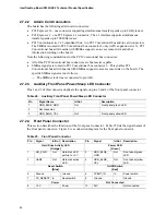
Page 48: ...on the board The specific SMBus signals are as follows The SMBus clock line is connected to pin A40 2 7 2 3 Auxiliary Front Panel Power Sleep LED Connector Pins 1 and 3 of this connector duplicate the signals on pins 2 and 4 of the front panel connector Table 24 Auxiliary Front Panel Power Sleep LED Connector Pin Signal Name In Out Description 1 HDR_BLNK_GRN Out Front panel green LED 2 Not connect...

Page 49: ...TA connector An IDE hard drive connected to an onboard IDE connector 2 7 2 4 2 Reset Switch Connector Blue Pins 5 and 7 Blue can be connected to a momentary single pole single throw SPST type switch that is normally open When the switch is closed the board resets and runs the POST 2 7 2 4 3 Power Sleep LED Connector Green Pins 2 and 4 Green can be connected to a one or two color LED Table 26 shows...

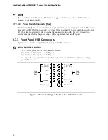
Page 50: ...l debounce circuitry on the board At least two seconds must pass before the power supply will recognize another on off signal 2 7 3 Front Panel USB Connectors Figure 9 is a connection diagram for the front panel USB connectors INTEGRATOR S NOTES The 5 V DC power on the USB connector is fused Pins 1 3 5 and 7 comprise one USB port Pins 2 4 6 and 8 comprise one USB port Use only a front panel USB co...

Page 51: ...ecovery When the jumper is set to configure mode and the computer is powered up the BIOS compares the processor version and the microcode version in the BIOS and reports if the two match OM19011 1 3 Figure 10 Location of the Jumper Block Table 28 BIOS Setup Configuration Jumper Settings Function Mode Jumper Setting Configuration Normal 1 2 1 3 The BIOS uses current configuration information and pa...

Page 52: ...llustrates the mechanical form factor of the board Dimensions are given in inches millimeters The outer dimensions are 9 60 inches by 8 60 inches 243 84 millimeters by 218 44 millimeters Location of the I O connectors and mounting holes are in compliance with the ATX specification OM19012 6 10 154 94 2 10 53 34 3 15 80 01 6 45 163 83 6 50 165 10 5 20 132 08 1 00 45 72 0 00 0 00 Figure 11 Board Dim...

Page 53: ... relative to chassis requirements are described in the ATX specification NOTE The I O shield drawing in this document is for reference only An I O shield compliant with the ATX chassis specification 2 03 is available from Intel Pictorial View Scale 1 000 20 0 254 TYP 0 787 0 10 162 3 REF 6 390 159 2 0 12 6 268 0 005 1 6 0 12 0 063 0 005 1 55 REF 0 061 8x R 0 5 MIN 12 04 0 474 7 01 0 276 Ø 1 00 0 0...

Page 54: ...s but are based on the minimum and maximum current draw possible from the board s power delivery subsystems to the processor memory and USB ports Use the datasheets for add in cards such as PCI to determine the overall system power requirements The selection of a power supply at the system level is dependent on the system s usage model and not necessarily tied to a particular processor speed Table...

Page 55: ...ION The 5 V standby line for the power supply must be capable of providing adequate 5 V standby current Failure to do so can damage the power supply The total amount of standby current required depends on the wake devices supported and manufacturing options System integrators should refer to the power usage values listed in Table 29 when selecting a power supply for use with the board Additional p...

Page 56: ... some instances damage to the board For a list of chassis that have been tested with Intel desktop boards please refer to the following website http developer intel com design motherbd cooling htm All responsibility for determining the adequacy of any thermal or system design remains solely with the reader Intel makes no warranties or representations that merely following the instructions presente...

Page 57: ...or circuit The processor voltage regulator area item A in Figure 14 can reach a temperature of up to 85 o C in an open chassis Figure 14 shows the locations of the localized high temperature zones OM19013 B A D C Item Description A Processor voltage regulator area B Processor C ATI Radeon Xpress 200 Northbridge D IXP 450 Southbridge Figure 14 Localized High Temperature Zones ...

Page 58: ...erature see processor datasheets and processor specification updates ATI Radeon Xpress 200 Northbridge 95 o C IXP 450 Southbridge 85 o C For information about Refer to Intel Pentium 4 processor datasheets and specification updates Section 1 1 4 page 14 2 12 Reliability The Mean Time Between Failures MTBF prediction is calculated using component and subassembly random failure rates The calculation ...

Page 59: ... C Shock Unpackaged 50 g trapezoidal waveform Velocity change of 170 inches second Packaged Half sine 2 millisecond Product Weight pounds Free Fall inches Velocity Change inches sec 20 36 167 21 40 30 152 41 80 24 136 81 100 18 118 Vibration Unpackaged 5 Hz to 20 Hz 0 01 g Hz sloping up to 0 02 g Hz 20 Hz to 500 Hz 0 02 g Hz flat Packaged 5 Hz to 40 Hz 0 015 g Hz flat 40 Hz to 500 Hz 0 015 g Hz sl...

Page 60: ...equirements USA and Canada EN 60950 1 2002 Information Technology Equipment Safety Part 1 General Requirements European Union IEC 60950 1 2001 First Edition Information Technology Equipment Safety Part 1 General Requirements International 2 14 2 European Union Declaration of Conformity Statement We Intel Corporation declare under our sole responsibility that the product Intel Desktop Board D102GGC...

Page 61: ...ins númer 89 336 EEC 73 23 EEC Italiano Questo prodotto è conforme alla Direttiva Europea 89 336 EEC 73 23 EEC Latviešu Šis produkts atbilst Eiropas Direktīvu 89 336 EEC un 73 23 EEC noteikumiem Lietuvių Šis produktas atitinka Europos direktyvų 89 336 EEC ir 73 23 EEC nuostatas Malti Dan il prodott hu konformi mal provvedimenti tad Direttivi Ewropej 89 336 EEC u 73 23 EEC Norsk Dette produktet er ...

Page 62: ...地点作 恰当的重复使用处理 请参考http www intel com intel other ehs product_ecology Recycling_Program htm 了解此计划的详情 包括涉及产品之范围 回收地点 运送指导 条款和条件等 Deutsch Als Teil von Intels Engagement für den Umweltschutz hat das Unternehmen das Intel Produkt Recyclingprogramm implementiert das Einzelhandelskunden von Intel Markenprodukten ermöglicht gebrauchte Produkte an ausgewählte Standorte für ordnungsgemäßes Recycling zurückzu...

Page 63: ...tul Sila rujuk http www intel com intel other ehs product_ecology Recycling_Program htm untuk mendapatkan butir butir program ini termasuklah skop produk yang dirangkumi lokasi lokasi tersedia arahan penghantaran terma syarat dsb Portuguese Como parte deste compromisso com o respeito ao ambiente a Intel implementou o Programa de Reciclagem de Produtos para que os consumidores finais possam enviar ...

Page 64: ...ain discrete components used on the board contain a small amount of lead which is necessary for component performance and or reliability This desktop board is referred to as Lead free second level interconnect The board substrate and the solder connections from the board to the components second level connections are all lead free Table 34 shows the various forms of the Lead Free 2nd Level Interco...

Page 65: ...Compatibility Australia and New Zealand CISPR 22 3rd Edition Class B Limits and methods of measurement of Radio Disturbance Characteristics of Information Technology Equipment International CISPR 24 1997 Information Technology Equipment Immunity Characteristics Limits and Methods of Measurement International VCCI Class B Voluntary Control for Interference by Information Technology Equipment Japan ...

Page 66: ...ean Union EU EMC directive 89 336 EEC and Low Voltage directive 73 23 EEC Australian Communications Authority ACA C tick mark Includes adjacent Intel supplier code number N 232 Japan VCCI Voluntary Control Council for Interference mark S Korea MIC Ministry of Information and Communication mark Includes adjacent MIC certification number CPU D102GGC2 For information about MIC certification go to htt...

Page 67: ...OST identifying the type of BIOS and a revision code The initial production BIOSs are identified as GC11020M 86A When the BIOS Setup configuration jumper is set to configure mode and the computer is powered up the BIOS compares the CPU version and the microcode version in the BIOS and reports if the two match The BIOS Setup program can be used to view and change the BIOS settings for the computer ...

Page 68: ...h Memory Organization The Firmware Hub FWH includes a 4 Mbit 512 KB flash memory device 3 3 Resource Configuration 3 3 1 PCI Autoconfiguration The BIOS can automatically configure PCI devices PCI devices may be onboard or add in cards Autoconfiguration lets a user insert or remove PCI cards without having to configure the system When a user turns on the system after adding a PCI card the BIOS auto...

Page 69: ...OS enables applications such as third party management software to use SMBIOS The BIOS stores and reports the following SMBIOS information BIOS data such as the BIOS revision level Fixed system data such as peripherals serial numbers and asset tags Resource data such as memory size cache size and processor speed Dynamic data such as event detection and error logging Non Plug and Play operating sys...

Page 70: ...eation of a boot diskette and manual rebooting of the system Using this utility the BIOS can be updated from a file on a 1 44 MB diskette from a legacy diskette drive or an LS 120 diskette drive or a CD ROM Both utilities verify that the updated BIOS matches the target system to prevent accidentally installing an incompatible BIOS NOTE Review the instructions distributed with the upgrade utility b...

Page 71: ...r a network add in card with a remote boot ROM installed Pressing the F12 key during POST automatically forces booting from the LAN To use this key during POST the User Access Level in the BIOS Setup program s Security menu must be set to Full 3 7 3 Booting Without Attached Devices For use in embedded applications the BIOS has been designed so that after passing the POST the operating system loade...

Page 72: ...the following BIOS Setup program settings reduces the POST execution time In the Boot Menu set the hard disk drive as the first boot device As a result the POST does not first seek a diskette drive which saves about one second from the POST execution time In the Peripheral Configuration submenu disable the LAN device if it will not be used This can reduce up to four seconds of option ROM boot time...

Page 73: ...assword prompt will be displayed before the computer is booted If only the supervisor password is set the computer boots without asking for a password If both passwords are set the user can enter either password to boot the computer For enhanced security use different passwords for the supervisor and user passwords Valid password characters are A Z a z and 0 9 Passwords may be up to 16 characters ...

Page 74: ...Intel Desktop Board D102GGC2 Technical Product Specification 74 ...

Page 75: ...odes Type Pattern Frequency Memory error Three long beeps 1280 Hz Thermal warning Four alternating beeps High tone low tone high tone low tone High tone 2000 Hz Low tone 1600 Hz 4 3 BIOS Error Messages Table 42 lists the error messages and provides a brief description of each Table 42 BIOS Error Messages Error Message Explanation CMOS Battery Low The battery may be losing power Replace the battery...

Page 76: ...bles listed above all POST codes and range values are listed in hexadecimal Table 43 Port 80h POST Code Ranges Range Category Subsystem 00 0F Debug codes Can be used by any PEIM driver for debug 10 1F Host Processors 1F is an unrecoverable CPU error 20 2F Memory Chipset 2F is no memory detected or no useful memory detected 30 3F Recovery 3F indicated recovery failure 40 4F Reserved for future use ...

Page 77: ...ontroller and the DIMMs 25 Configuring memory 26 Optimizing memory settings 27 Initializing memory such as ECC init 28 Testing memory PCI Bus 50 Enumerating PCI busses 51 Allocating resources to PCI bus 52 Hot Plug PCI controller initialization 53 57 Reserved for PCI Bus USB 58 Resetting USB bus 59 Reserved for USB ATA ATAPI SATA 5A Resetting PATA SATA bus and all devices 5B Reserved for ATA SMBus...

Page 78: ...ixed Media B0 Resetting fixed media B1 Disabling fixed media B2 Detecting presence of a fixed media IDE hard drive detection etc B3 Enabling configuring a fixed media Removable media B8 Resetting removable media B9 Disabling removable media BA Detecting presence of a removable media IDE CD ROM detection etc BC Enabling configuring a removable media BDS Dy Trying boot selection y y 0 to 15 PEI Core...

Page 79: ...F TBD Unrecoverable Boot failure S3 resume failure Runtime Phase EFI OS Boot F4 Entering Sleep state F5 Exiting Sleep state F8 EFI boot service ExitBootServices has been called F9 EFI runtime service SetVirtualAddressMap has been called FA EFI runtime service ResetSystem has been called PEIMs Recovery 30 Crisis Recovery has initiated per User request 31 Crisis Recovery has initiated by software co...

Page 80: ...ization 13 SMM initialization 50 Enumerating PCI busses 51 Allocating resourced to PCI bus 92 Detecting the presence of the keyboard 90 Resetting keyboard 94 Clearing keyboard input buffer 95 Keyboard Self Test EB Calling Video BIOS 58 Resetting USB bus 5A Resetting PATA SATA bus and all devices 92 Detecting the presence of the keyboard 90 Resetting keyboard 94 Clearing keyboard input buffer 5A Re...

Reviews: