


Intel Desktop Board DB85FL Technical Product Specification
70
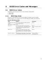
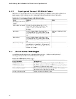
4.1.2
Front-panel Power LED Blink Codes
Whenever a recoverable error occurs during POST, the BIOS causes the board’s front
panel power LED to blink an error code describing the problem (see Table 39).
Table 39. Front-panel Power LED Blink Codes
Type
Pattern
Note
F2 Setup/F10 Boot Menu
Prompt
None
BIOS update in progress Off when the update begins, then on for
0.5 seconds, then off for 0.5 seconds. The
pattern repeats until the BIOS update is
complete.
Video error
On-off (1.0 second each) two times, then
2.5-second pause (off), entire pattern repeats
(blink and pause) until the system is powered
off.
When no VGA option ROM is
found.
Memory error
On-off (1.0 second each) three times, then
2.5-second pause (off), entire pattern repeats
(blinks and pause) until the system is powered
off.
Thermal trip warning
Each beep will be accompanied by the following
blink pattern: .25 seconds on, .25 seconds off,
.25 seconds on, .25 seconds off. This will result
in a total of 16 blinks.
4.2
BIOS Error Messages
The BIOS also displays error messages during POST. Table 40 lists the error
messages and provides a brief description of each.
Table 40. BIOS Error Messages
Error Message
Explanation
CMOS Battery Low
The battery may be losing power. Replace the battery soon.
CMOS Checksum Bad
The CMOS checksum is incorrect. CMOS memory may have been
corrupted. Run Setup to reset values.
Memory Size Decreased
Memory size has decreased since the last boot. If no memory
was removed, then memory may be bad.
No Boot Device Available
System did not find a device to boot.


