13
Hardware Installation and Network Topology
C H A P T E R
1
Excessive flow control problems
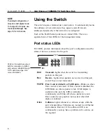
During times of peak network usage, you may occasionally see the
FC/FD LED blink (for a description of the LED, see page 6). This is
normal. However, if it stays lit for more than a few seconds at a time,
or if there’s an excessive number of flow controls reported by the
network management software, it could indicate a problem with your
network configuration.
A port’s FC/FD LED indicator flashes whenever a packet is received
that needs to be forwarded to a port that already has too many packets
queued. This indicates a temporary overload situation on one port; the
total traffic to the port exceeds the amount the buffer can hold. This
typically occurs when there are several fast machines on different
ports trying to access a machine across the switch. If this is
infrequent, you don’t need to do anything. However, if this occurs
often on the network, then the devices causing flow control to activate
should be identified and moved to the same segment as the device that
they are talking to.
When Ethernet bandwidth is temporarily insufficient for the traffic,
there are only three possible actions: drop packets, use flow control,
or segment the network. Buffering packets only works for a very short
while. An extended overload will eventually overflow buffers and
cause dropped packets. Flow control stops transmission on a port and
forces devices to resend packets, ensuring that packets aren’t lost.
This is the most reasonable solution, since it relies on Ethernet’s
inherent collision detection mechanism to relieve temporary overload.
Repeater count limitations
The switch doesn’t count as a repeater. Each port on the switch can
support a full Fast Ethernet network. There can be one repeater/hub
between the switch and any workstations or servers (a stack of Intel
Express 100BASE-TX Hubs counts as a single hub). Also, the total
diameter of a segment can’t exceed 200 meters when using UTP
cable. That is, the distance between any two nodes on a segment (or
the switch and a node on the other side of a hub) can’t exceed 200
meters.
NOTE
By default, flow control is
enabled on all ports.
If you configure a port for full
duplex, flow control is auto-
matically disabled.
Summary of Contents for Express 100BASE-TX
Page 1: ...Intel Express 100BASE TX Switching Hub User Guide Part No 654655 001 ...
Page 18: ......
Page 62: ......
Page 76: ......


