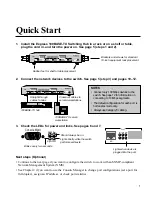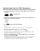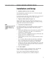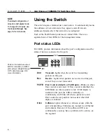
5
Hardware Installation and Network Topology
C H A P T E R
1
Installation and Setup
1
Install the switch in a rack or on a shelf.
For rack placement, connect the switch to a 19-inch rack using the
enclosed rack mount brackets.
For shelf placement, attach the enclosed rubber feet to each corner of
the bottom of the switch and place it on a flat, level surface.
2
Plug the switch in and turn the power on.
Plug the switch into an active AC outlet and turn the power on. A
built-in power supply automatically adjusts to any outlet providing
between 90 VAC and 264 VAC at 50/60 Hz.
3
Connect the Fast Ethernet devices.
For optimum performance, the Fast Ethernet segments connected to
the switch must be configured carefully. Follow these general
guidelines:
•
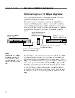
Connect only 100 Mbps devices to the switch. The switch will not
work with 10 Mbps devices. See page 12 for information on
connecting to a 10 Mbps segment.
•
Always use Category 5 unshielded twisted-pair (UTP) cable when
plugging devices into 100BASE-TX ports.
•
Limit the distance between devices connected with UTP cable to
100 meters.
•
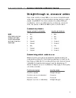
Use a crossover cable when directly connecting a workstation,
server, or another switch to the switch. Use straight-through
cables when connecting to a repeating hub or concentrator.
•
Configure the network so devices that primarily talk to each other
are on the same segment. Each port on the switch is defined as a
single Fast Ethernet segment.
4
Is setup complete?
If you’re using the switch as a stand-alone device (not under the
control of network management software), you’re done.
If you want to change the default configuration (shown in
Appendix A) or manage the switch, continue to Chapter 2.
NOTE
The switch will only work with
100 Mbps devices. For a
10BASE-T connection, see
page 12.
Summary of Contents for Express 100BASE-TX
Page 1: ...Intel Express 100BASE TX Switching Hub User Guide Part No 654655 001 ...
Page 18: ......
Page 62: ......
Page 76: ......


