16
Intel
®
Storage System SSR316MJ2 Cable Kit
Remove I
2
C Cables from System
A.
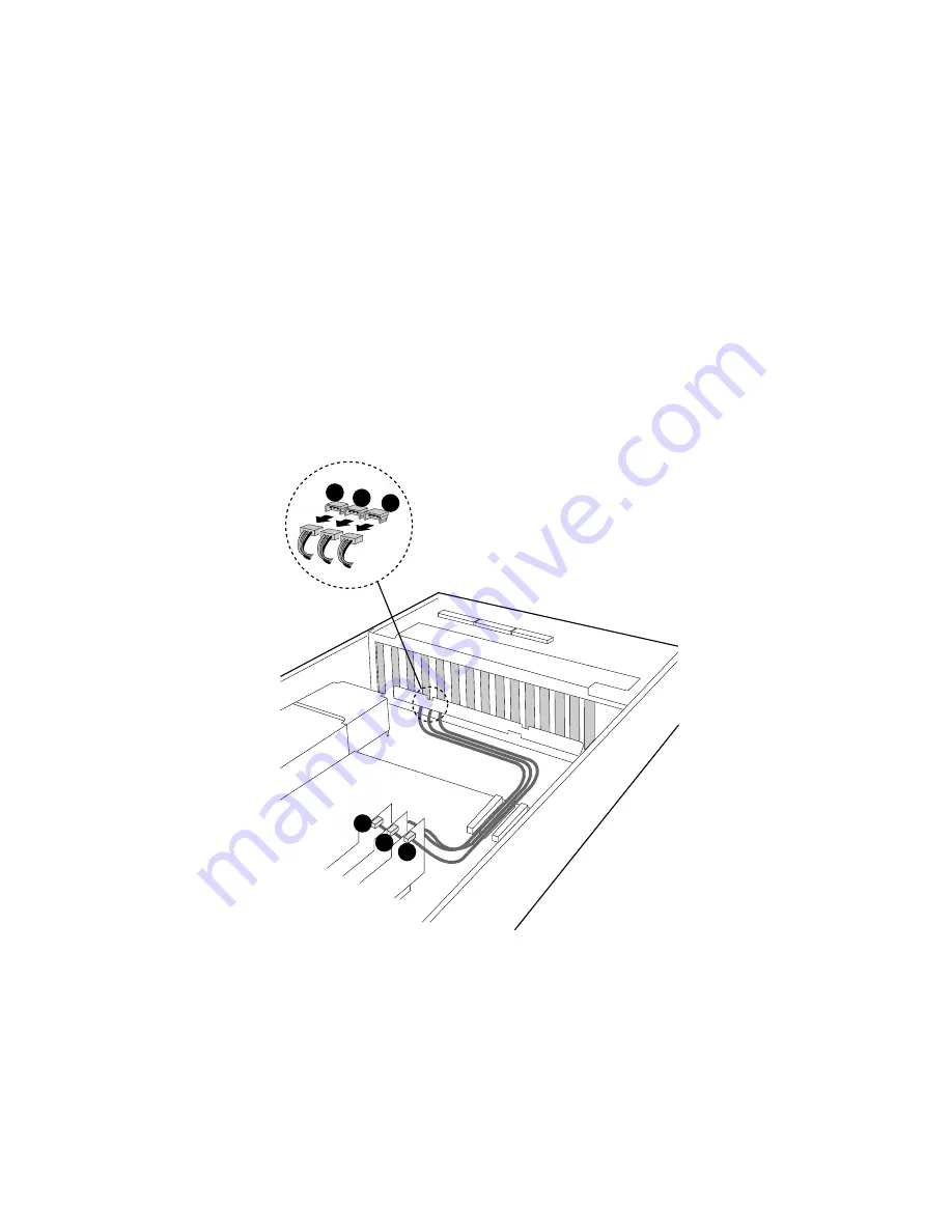
Make a note of the header positions of the three I
2
C Cable connectors. After installation of the
SATA Cables has been completed, you will re-connect these connectors to the same headers.
Carefully remove the I
2
C Cable connector labeled JP4 from its I
2
C Cable header on the
backplane board. Carefully remove the I
2
C Cable connector labeled SL2J6 from its I
2
C Cable
header in the HBA Card set. See Figure 7.
B.
Carefully remove the I
2
C Cable connector labeled JP6 from its I
2
C Cable header on the
backplane board. Carefully remove the I
2
C Cable connector labeled SL3J6 from its I
2
C Cable
header in the HBA Card set. See Figure 7.
C.
Carefully remove the I
2
C Cable connector labeled JP7 from its I
2
C Cable header on the
backplane board. Carefully remove the I
2
C Cable connector labeled SL4J6 from its I
2
C Cable
header in the HBA Card set. See Figure 7. Set the I
2
C Cable connectors on a static-free surface.
A
B
C
A
B
C
Figure 7. Removing the I
2
C Cables from the Backplane Board


