Intel
®
Storage System SSR316MJ2 Cable Kit
v
Figure 23. Removing Chassis Cover .................................................................................... 33
Remove Front Panel Cables from Front Panel Board........................................................... 34
Remove Front Panel Cables from Baseboard ...................................................................... 35
Install Front Panel Cables on Baseboard.............................................................................. 36
Re-seat Front Panel Board Cables ....................................................................................... 37
Finishing Up .......................................................................................................................... 38
I
2
C Cables Installation Procedures.................................................................. 39
Required Tools...................................................................................................................... 39
Power Down System and Remove Chassis Cover ............................................................... 39
Figure 29. Removing Chassis Cover .................................................................................... 39
Remove Front Panel Cables from Front Panel Board........................................................... 40
Remove Phillips Screws from Fan Assembly........................................................................ 41
Remove Fan Connectors from Baseboard............................................................................ 42
Remove Fan Assembly from the System.............................................................................. 43
Remove I
2
C Cables from System ......................................................................................... 44
Installing I
2
C Cables in the System ....................................................................................... 45
Re-insert Fan Assembly into System .................................................................................... 46
Re-attach Fan Assembly to System...................................................................................... 47
Re-attach System Fan Assembly Connectors to Baseboard ................................................ 48
Re-seat Front Panel Board Cables ....................................................................................... 49
Finishing Up .......................................................................................................................... 50
Figures
Figure 1. Removing Chassis Cover ............................................................................................10
Figure 2. Unseat Hard Disk Drives and Hard Disk Drive Carriers ..............................................11
Figure 3. Removing Front Panel Cables.....................................................................................12
Figure 4. Removing Phillips Screws to Release the Fan Assembly............................................13
Figure 5. Removing Fan Connectors from the Baseboard .........................................................14
Figure 6. Removing Fan Assembly and SATA Cable Connectors..............................................15
Figure 7. Removing the I
2
C Cables from the Backplane Board ..................................................16
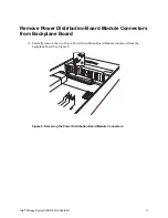
Figure 8. Removing the Power Distribution Board Module Connectors......................................17
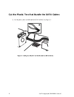
Figure 9. Cutting the Plastic Ties that Bundle the SATA Cables ................................................18
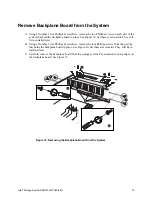
Figure 10. Removing the Backplane Board from the System .....................................................19
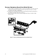
Figure 11. Removing the Backplane Board from the Metal Shroud............................................20
Figure 12. Installing New Backplane Board into Metal Shroud ...................................................21
Figure 13. Re-connecting the I
2
C Cables....................................................................................22
Figure 14. Re-Connecting the Power Distribution Board Module Connectors ............................23
Figure 15. Installing the New Backplane Board in the System ...................................................24
Figure 16. Connecting the SATA Cables to the HBA Cards .......................................................25


