PROCEDURE CALLS
7-20
7.8
RETURNS
The return (
ret
) instruction provides a generalized return mechanism that can be used to return
from any procedure that was entered by
call
,
calls
,
callx
, an interrupt call or a fault call. When
ret
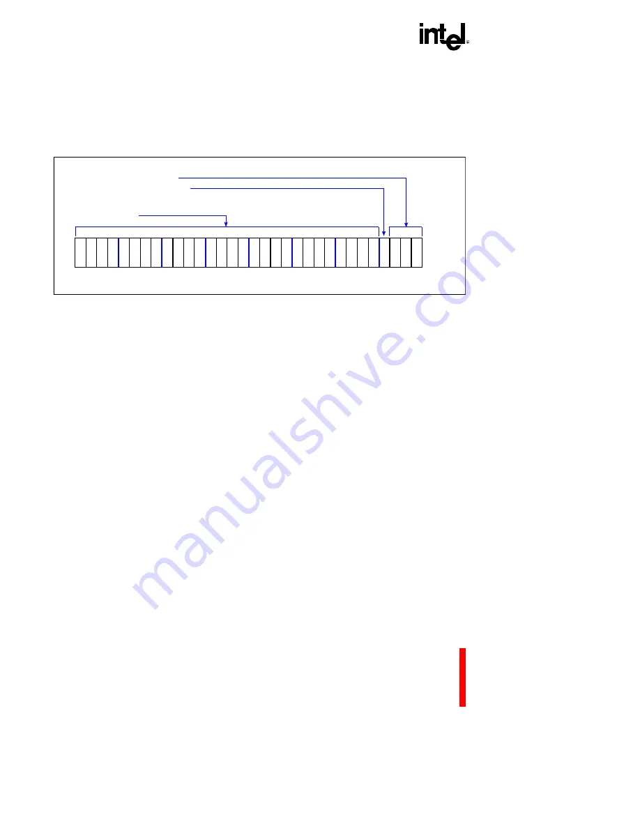
executes, the processor uses the information from the return-type field in the PFP register
(
Figure 7-5
) to determine the type of return action to take.
Figure 7-5. Previous Frame Pointer Register (PFP) (r0)
return-type field indicates the type of call which was made.
Table 7-2
shows the return-type field
encoding for the various calls: local, supervisor, interrupt and fault.
trace-on-return flag (PFP.rt0 or bit 0 of the return-type field) stores the trace enable bit value when
an explicit system-supervisor call is made from user mode. When the call is made, the PC register
trace enable bit is saved as the trace-on-return flag and then replaced by the trace controls bit in the
system procedure table. On a return, the trace enable bit’s original value is restored. This
mechanism allows instruction tracing to be turned on or off when a supervisor mode switch
occurs. See
section 9.5.2.1, “Tracing on Explicit Call” (pg. 9-13)
.
prereturn-trace flag (PFP.p) is used in conjunction with call-trace and prereturn-trace modes.
When call-trace mode is enabled when a call is made, the processor sets the prereturn-trace flag;
otherwise it clears the flag. Then, when this flag is set and prereturn-trace mode is enabled, a
prereturn trace event is generated on a return, before any actions associated with the return
operation are performed. See
section 9.2, “TRACE MODES” (pg. 9-3)
for a discussion of
interaction between call-trace and prereturn-trace modes with the prereturn-trace flag.
28
24
20
16
12
8
4
0
31
Return Status
a
4
p
r
t
2
r
t
1
r
t
0
Return-Type Field - PFP.rt
Pre-Return-Trace Flag - PFP.p
Previous Frame Pointer
Address-PFP.a
a
3
1
Summary of Contents for i960 Jx
Page 1: ...Release Date December 1997 Order Number 272483 002 i960 Jx Microprocessor Developer s Manual ...
Page 24: ......
Page 25: ...1 INTRODUCTION ...
Page 26: ......
Page 35: ...2 DATA TYPES AND MEMORY ADDRESSING MODES ...
Page 36: ......
Page 46: ......
Page 47: ...3 PROGRAMMING ENVIRONMENT ...
Page 48: ......
Page 73: ...4 CACHE AND ON CHIP DATA RAM ...
Page 74: ......
Page 85: ...5 INSTRUCTION SET OVERVIEW ...
Page 86: ......
Page 111: ...6 INSTRUCTION SET REFERENCE ...
Page 112: ......
Page 233: ...7 PROCEDURE CALLS ...
Page 234: ......
Page 256: ......
Page 257: ...8 FAULTS ...
Page 258: ......
Page 291: ...9 TRACING AND DEBUGGING ...
Page 292: ......
Page 309: ...10 TIMERS ...
Page 310: ......
Page 324: ......
Page 325: ...11 INTERRUPTS ...
Page 326: ......
Page 369: ...12 INITIALIZATION AND SYSTEM REQUIREMENTS ...
Page 370: ......
Page 412: ......
Page 413: ...13 MEMORY CONFIGURATION ...
Page 414: ......
Page 429: ...14 EXTERNAL BUS ...
Page 430: ......
Page 468: ......
Page 469: ...15 TEST FEATURES ...
Page 470: ......
Page 493: ...A CONSIDERATIONS FOR WRITING PORTABLE CODE ...
Page 494: ......
Page 502: ......
Page 503: ...B OPCODES AND EXECUTION TIMES ...
Page 504: ......
Page 515: ...C MACHINE LEVEL INSTRUCTION FORMATS ...
Page 516: ......
Page 523: ...D REGISTER AND DATA STRUCTURES ...
Page 524: ......
Page 550: ......
Page 551: ...GLOSSARY ...
Page 552: ......
Page 561: ...INDEX ...
Page 562: ......
Page 578: ......


