106
Hardware Design Guide
IXP28XX Network Processor
MSF (SPI-4/CSIX/FC)
5.3
Simulation Results for LVDS Signals on IXDP2800
Advanced Development Platform
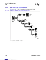
Figure 61
illustrates the connections between the IXP28XX network processor and an LVDS load
device showing two unique, connected PCBs:
Table 36
provides network length results for Topology 1. The table illustrates the resulting data
EYE opening from simulations of the topology shown in
Figure 61
.
Figure 62
illustrates the connections between the IXP28XX network processor and an LVDS load
device showing two unique, connected PCBs with a loopback signal and connectors in each path.
Figure 61.
Topology 1 - Two Unique PCBs Connected
B3404-01
LVDS
Load
Device
Topology 1
Two unique PCBs connected via a connector.
Intel
®
IXP2800
Network
Processor
L1
L2
Connector
Table 36.
Topology 1 Network Length Results
Transfer Net
L1 (inches)
L2 (inches)
EYE Opening (mV)
SPI4_RX
1.5 to 3
3 to 7
210
SPI4_RX_CLK
1.5 to 3
3 to 7
230
SPI4_TX
3 to 7
1.5 to 3
260
SPI4_TX_CLK
3 to 7
1.5 to 3
280
Downloaded from
Elcodis.com
electronic components distributor


