26
Hardware Design Guide
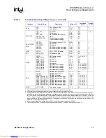
IXP28XX Network Processor
Power Ratings and Requirements
2.3
LC Filter Network
Figure 3
shows an example of an LC filter design that can be used to derive the power for the
analog and DLL power supplies for the IXP2800 or IXP2850 network processor. For L1, a 10-
Ω
ferrite bead with a DCR of less than 0.1
Ω
should be used. For C1, a 10 µF capacitor should be
used and each analog V
CC
pin should be decoupled with a 0.1 µF and a 0.01 µF capacitor.
The IXDP2800 Advanced Development Platform uses analog power for all PLL/DL pins.
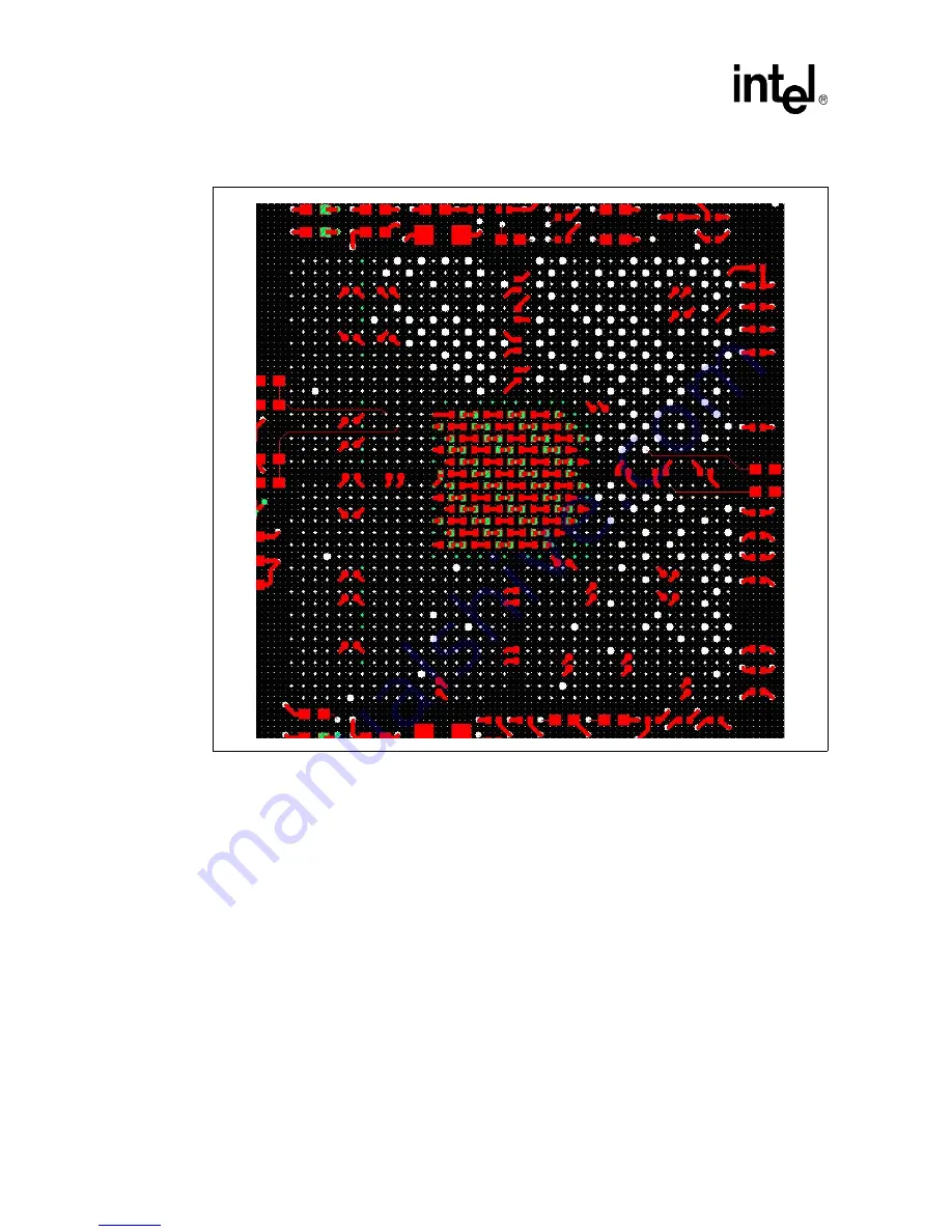
Figure 2.
IXDP2800 Decoupling Implementation
Downloaded from
Elcodis.com
electronic components distributor


