IXP28XX Network Processor
Contents
7
69
SPCI Address/Data Signals with IDSEL Signal Topology ........................................................ 118
70
cPCI Signal Topology ............................................................................................................... 120
71
IXDP2800 PCI Bus Topology Block Diagram ........................................................................... 121
72
64-Bit PCI Bus Routing Between Processors........................................................................... 122
73
64-bit PCI Bus Routing from IXP28XX Network Processor to Bridge....................................... 123
74
Generic Slowport Connection ................................................................................................... 127
75
Example Ingress IXP28XX Network Processor Slowport Configuration...................................128
76
Example Egress IXP28XX Slowport Configuration...................................................................129
77
CPLD Implementation of a Flash EEPROM Interface .............................................................. 129
78
Slowport Control Signals Topology........................................................................................... 131
79
Slowport Clock Topology ..........................................................................................................132
80
Slowport Address/Data Topology .............................................................................................133
81
Slowport Application Topology ................................................................................................. 135
82
Mode 0 Single Write Transfer for a Fixed-timed Device ........................................................... 135
83
Mode 0 Single Write Transfer for a Self-timing Device.............................................................136
84
An Interface Topology with Intel / AMCC* SONET/SDH Device .............................................. 139
85
Mode 3 32-Bit Write Transfer....................................................................................................140
86
Slowport Mode 3 write example showing TXE +1 delay using SP_TXE .................................. 141
87
Mode 32-Bit Read Transfer ...................................................................................................... 142
88
Slowport Mode 3 read example showing RXE = 2 ...................................................................143
89
Intel® IXP2800 Network Processor Package Marking .............................................................148
90
Intel® IXP2850 Network Processor Package Marking .............................................................148
91
Intel® IXP2800 or Intel® IXP2850 Network Processor Package Ball Grid Array ..................... 149
92
Intel® IXP2800 or Intel® IXP2850 Network Processor Package Side View.............................149
93
Intel® IXP2800 or Intel® IXP2850 Network Processor Package Top View.............................. 150
Tables
1
Product Features of IXP28XX Network Processors ................................................................... 12
2
Guide Conventions ..................................................................................................................... 14
3
Acronyms and Terminology ........................................................................................................ 14
4
Absolute Maximum/Minimum Ratings Table .............................................................................. 17
5
Functional Operating Temperature Range ................................................................................. 17
6
Typical and Maximum Power......................................................................................................18
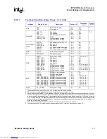
7
Functional Operating Voltage Range – 1.4/1.0 GHz .................................................................. 19
8
Functional Operating Voltage Range – 650 MHz ....................................................................... 20
9
Example Power by Supply – 1.4 GHz.........................................................................................21
10
Example Power by Supply – 1.0 GHz.........................................................................................22
11
Example Power by Supply – 650 MHz ....................................................................................... 23
12
RDRAM Subsystem Implementation Options............................................................................. 34
13
Package Trace Lengths for RDRAM Signals.............................................................................. 50
14
SRAM Controller Configurations................................................................................................. 55
15
QDR Address/RPE/WPE Mapping ............................................................................................. 55
16
Total Memory per Channel ......................................................................................................... 55
17
An Overview of QDR signal groups ............................................................................................ 62
18
QDR SRAM Signal Mapping....................................................................................................... 62
19
QDR Address Signal Group Routing Guidelines ........................................................................ 67
20
QDR Address Stack-up Signal Cross-section Details ................................................................ 68
21
QDR D Signal Group Routing Guidelines................................................................................... 69
22
QDR D Stack-up Signal Cross-section Details ........................................................................... 69
23
QDR Q (Data In) Signal Group Routing Guidelines.................................................................... 70
Downloaded from
Elcodis.com
electronic components distributor


