background image

JBOD 2000 Internal Connection Overview 

Intel® Storage Server System JBOD 2000 Family Hardware Guide 


Revision 1.42 

36 


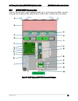
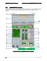
Figure 32. Internal SAS Expander Location 


Summary of Contents for JBOD 2000 Family

Page 1: ...Intel Storage Server System JBOD 2000 Family Hardware Guide Revision 1 42 November 2015 ...

Page 2: ... external connection mode November 2013 1 2 Removed JBOD2224S2SP 2 5 single port SKU related content March 2014 1 3 Removed original section 4 6 13 about power recovery September 2014 1 4 Removed the description of SMBus connector on the HSBP as they are not used January 2015 1 41 Removed qualified mini SAS cable list as many models have been EOL ed by vendors November 2015 1 42 Removed PSU Cold R...

Page 3: ...NEYS FEES ARISING OUT OF DIRECTLY OR INDIRECTLY ANY CLAIM OF PRODUCT LIABILITY PERSONAL INJURY OR DEATH ARISING IN ANY WAY OUT OF SUCH MISSION CRITICAL APPLICATION WHETHER OR NOT INTEL OR ITS SUBCONTRACTOR WAS NEGLIGENT IN THE DESIGN MANUFACTURE OR WARNING OF THE INTEL PRODUCT OR ANY OF ITS PARTS Intel may make changes to specifications and product descriptions at any time without notice Designers...

Page 4: ...ve Support 15 3 2 1 3 5 Drive Hot Swap Backplane Overview 16 3 2 2 Cypress CY8C22545 Enclosure Management Controller 17 4 Power Subsystem 18 4 1 Power Distribution Board PDB 19 4 2 Mechanical Overview 23 4 3 Power Connectors 24 4 3 1 Power Supply Module Card Edge Connector 24 4 3 2 Hot Swap Backplane Power Connector 25 4 4 Power Supply Module Efficiency 25 4 5 AC Power Cord Specification Requireme...

Page 5: ...6 2 JBOD SAS Interface Board 37 6 2 1 JBOD SAS Interface Board Port Numbering 37 6 3 Pin outs 38 6 3 1 JBOD2312S2SP Interconnection 39 6 3 2 JBOD2224S2DP Interconnection 42 7 JBOD 2000 External SAS Connection Mode Overview 45 7 1 External SAS Controller Support 45 7 2 External SAS Cable 45 7 3 Hard Drive Type 46 7 4 JBOD Cascade 46 7 5 Single port JBOD 2000 External Connection Mode 46 7 5 1 Single...

Page 6: ...e Bay 12 Drive Configuration 15 Figure 17 3 5 Drive Tray Assembly 15 Figure 18 Status and Activity LED on 3 5 Drive Tray 15 Figure 19 3 5 Hot Swap Backplane and Drive Bay Assembly 16 Figure 20 SFF 8482 Connector on 3 5 HSBP 16 Figure 21 Components on 3 5 HSBP 17 Figure 22 Power Supply Assembly 18 Figure 23 Power Distribution Board PDB 19 Figure 24 PDB Component Placement 20 Figure 25 Fan Fault LED...

Page 7: ... port JBOD 2000 47 Figure 42 Dual path Connection 48 Figure 43 Dual path with Cascaded JBOD 2000 48 Figure 44 Dual domain SAS for Dual port JBOD 2000 49 Figure 45 Two SAS Controllers Dual domain SAS Connection 50 Figure 46 Dual domain SAS for Cascaded Dual port JBOD 2000 50 Figure 47 Dual domain SAS for a Two node Cluster 51 Figure 48 Cascaded JBOD 2000 for a Two node Cluster 52 ...

Page 8: ...pecifications 25 Table 13 Power Factor 26 Table 14 AC Input Voltage Range 26 Table 15 AC Line Dropout Holdup 27 Table 16 AC Line Sag Transient Performance 27 Table 17 AC Line Surge Transient Performance 28 Table 18 Performance Criteria 28 Table 19 460 Watt Power Supply Over Current Protection 29 Table 20 Over Voltage Protection OVP Limits 30 Table 21 LED Indicators 31 Table 22 System Fan Connector...

Page 9: ...Intel Storage Server System JBOD 2000 Family Hardware Guide List of Tables Revision 1 42 ix This page intentionally left blank ...

Page 10: ......

Page 11: ...0 External SAS Connection Mode Overview Appendix A Qualified External Mini SAS Cable List Reference Documents 1 1 Server Product Use Disclaimer It is the responsibility of the system integrator who chooses not to use Intel developed server building blocks to consult vendor datasheets and operating parameters to determine the amount of airflow required for their specific application and environment...

Page 12: ... System JBOD 2000 Family Features that are unique to one product in the family are identified by denoting the full JBOD Product Code name Table 1 System Feature Set Intel Storage Server System JBOD 2000 Family Description JBOD2224S2DP 2U JBOD supports 24 x 2 5 drives with a dual port backplane JBOD2312S2SP 2U JBOD supports 12 x 3 5 drives with a single port backplane This chapter provides a high l...

Page 13: ...Intel Storage Server System JBOD 2000 Family Hardware Guide Product Family Overview Revision 1 42 3 Figure 2 12 x 3 5 Drive JBOD 2000 Product Drawing ...

Page 14: ...Product Family Overview Intel Storage Server System JBOD 2000 Family Hardware Guide Revision 1 42 4 2 1 Chassis Dimensions Figure 3 Chassis Dimensions ...

Page 15: ...imits Table 2 System Environmental Limits Summary Parameter Limits Temperature Operating ASHRAE Class A2 Continuous Operation 10ºC to 35ºC 1 50ºF to 95ºF with the maximum rate of change not to exceed 10ºC per hour ASHRAE Class A3 Includes operation up to 40ºC for up to 900 hrs per year ASHRAE Class A4 Includes operation up to 45ºC for up to 90 hrs per year Shipping 40ºC to 70ºC 40ºF to 158ºF Altit...

Page 16: ...o chooses not to use Intel developed server building blocks to consult vendor datasheets and operating parameters to determine the amount of airflow required for their specific application and environmental conditions Intel Corporation cannot be held responsible if components fail or the server board does not operate correctly when used outside any of its published operating or non operating limit...

Page 17: ...e Product Family Overview Revision 1 42 7 2 3 System Features and Options Overview Figure 4 System Components Overview 2 3 1 Hot Swap Hard Drive Bay and Front Panel Options Figure 5 12 x 3 5 Drive JBOD2000 Front View Figure 6 24 x 2 5 Drive JBOD2000 Front View ...

Page 18: ...on The System Status LED is a bi color Green Amber indicator that shows the current health of the server system The system provides two locations for this feature one is located on the Front Control Panel and the other is located on the back edge of the server board viewable from the back of the system Both LEDs are tied together and show the same state The System Status LED states are driven by t...

Page 19: ...Color State Criticality Description Amber Solid on SMBUS Alert Event Encountered P12V is out of its limits P5V is out of its limits A fan fault has been detected An over temperature event has been detected P3V3 is out of its limits Remote 1 and or Remote 2 temperature sensor is either open or shorted ...

Page 20: ... Label Description A SFF 8088 receptacle label A PRI B SFF 8088 receptacle label B PRI C PSU Figure 9 Dual port Backplane JBOD2000 Back View Label Description A SFF 8088 receptacle label A PRI B SFF 8088 receptacle label B PRI C SFF 8088 receptacle label A SEC D SFF 8088 receptacle label B SEC E SFF 8088 receptacle label C SEC F SFF 8088 receptacle label C PRI G PSU 1 H PSU 2 ...

Page 21: ...ve bay can support either SATA or SAS hard disk drives Mixing of drive types within a common hot swap backplane is not supported Systems with multiple hot swap backplanes can support different drive type configurations as long as the drives attached to a common backplane are the same and the installed controller attached to the given backplane can support the drive type Hard disk drive type is dep...

Page 22: ...re 12 Status and Activity LED on 2 5 Drive Tray Table 5 Drive Status LED States Amber Off No access and no fault Solid on Hard drive fault has occurred Blink RAID rebuild in progress 1 Hz Identify 2 Hz Table 6 Drive Activity LED States Green Condition Drive Type Behavior Power on with no drive activity SAS LED stays on SATA LED stays off Power on with drive activity SAS LED blinks off when process...

Page 23: ...orted by a given system SKU a system can be configured with one two or three 8 drive backplanes Each backplane is attached to the back of the drive bay assembly Figure 13 2 5 Hot Swap Backplane and Drive Bay Assembly On the front side of each backplane are mounted eight hard disk drive interface connectors A each providing both power and I O signals to the attached hard disk drives Figure 14 SFF 8...

Page 24: ...g SGPIO and I O signals for four SAS SATA hard drives on the backplane Cables can be routed from matching connectors on the server board installed add in SAS SATA RAID cards or optionally installed SAS expander cards for drive configurations of greater than eight hard drives D Power Harness Connector The backplane includes a 2x2 connector supplying power to the backplane Power is routed to each in...

Page 25: ...S Each 3 5 hard disk drive is mounted to a drive tray allowing for hot swap extraction and insertion Drive trays have a latching mechanism that is used to extract and insert the drives from the chassis and lock the tray in place Figure 17 3 5 Drive Tray Assembly Light pipes integrated into the drive tray assembly direct the light emitted from Amber drive status and Green activity LEDs located next...

Page 26: ... command Power on and drive spun down SAS LED stays off SATA LED stays off Power on and drive spinning up SAS LED blinks SATA LED stays off 3 2 1 3 5 Drive Hot Swap Backplane Overview Systems with 12 drive configurations have their own unique backplane The backplanes mount to the back of the drive bay assembly Figure 19 3 5 Hot Swap Backplane and Drive Bay Assembly On the front side of each backpl...

Page 27: ...s can be routed from matching connectors on the server board add in SAS SATA RAID cards or an optionally installed SAS expander card Each mini SAS connector includes a silk screen identifying which drives the connector supports Drives 0 3 Drives 4 7 and Drives 8 11 B Power Harness Connector The backplane includes a 2x2 connector supplying power to the backplane Power is routed to the backplane via...

Page 28: ...onfiguration total power available maybe less than twice the rated power of the installed power supply modules due to the amount of heat produced with both supplies providing peak power If system thermals exceed programmed limits platform management will attempt to keep the system operational Thermal support is open loop based on ambient temp sensor on the front panel The only power supply option ...

Page 29: ...Intel Storage Server System JBOD 2000 Family Hardware Guide Power Subsystem Revision 1 42 19 4 1 Power Distribution Board PDB Figure 23 Power Distribution Board PDB ...

Page 30: ...r B Expander SES 2 header G 2x12 pin front panel header C Expander power header H 1x5 aux header D FAN header J 2x12 SSI power connector E HSBP power header K power supply connector The PDB provides power from the power supply modules to the JBOD components and provides thermal monitoring and fan control and includes the following features The PDB connects to the power supply canister through two ...

Page 31: ...ments to ensure the fans run at the lowest possible speed for the given temperature The controller interfaces with two remote temp sensors and a local temp sensor built into the chip The thermal controller on the PDB is programmed using the SAS expander that comes with the Intel Storage Server System JBOD 2000 Family The SAS expander in the Intel Storage System JBOD 2000 Family uses a firmware tha...

Page 32: ...Power Subsystem Intel Storage Server System JBOD 2000 Family Hardware Guide Revision 1 42 22 Interrupt Register 2 for ADT7476 Bits 2 3 and 4 used for fan faults Figure 25 Fan Fault LED Block Diagram ...

Page 33: ...sure is 39 40mm x 74mm x 185mm The power supply contains a single 40mm fan The power supply has a card edge output that interfaces with a 2x25 card edge connector in the system The AC plugs directly into the external face of the power supply Figure 26 Power Supply Module Mechanical Drawing Figure 27 Power Supply Module Figure 28 AC Power Supply Connector View ...

Page 34: ...B1 GND A2 GND B2 GND A3 GND B3 GND A4 GND B4 GND A5 GND B5 GND A6 GND B6 GND A7 GND B7 GND A8 GND B8 GND A9 GND B9 GND A10 12V B10 12V A11 12V B11 12V A12 12V B12 12V A13 12V B13 12V A14 12V B14 12V A15 12V B15 12V A16 12V B16 12V A17 12V B17 12V A18 12V B18 12V A19 PMBus SDA B19 A0 SMBus address A20 PMBus SCL B20 A1 SMBus address A21 PSON B21 12V stby A22 SMBAlert B22 Cold Redundancy Bus A23 Retu...

Page 35: ...VA 4 Ground 8 P12V_240VA 4 4 Power Supply Module Efficiency The following table provides the required minimum efficiency level at various loading conditions These are provided at four different load levels 100 50 20 and 10 Efficiency is tested over an AC input voltage range of 115 VAC to 220 VAC Table 11 460 Watt Power Supply Efficiency Gold Loading 100 of Maximum 50 of Maximum 20 of Maximum 10 of...

Page 36: ...tage range is measured at 180VAC at max load 3 This requirement is not to be used for determining agency input current markings 4 6 3 AC Line Isolation Requirements The power supply meets all safety agency requirements for dielectric strength Transformers isolation between primary and secondary windings complies with the 3000VAC 4242VDC dielectric strength criteria If the working voltage between p...

Page 37: ...ied maximum input current The peak inrush current is less than the ratings of its critical components including input fuse bulk rectifiers and surge limiting device The power supply meets the inrush requirements for any rated AC voltage during turn on at any phase of AC voltage during a single cycle AC dropout condition as well as upon recovery after AC dropout of any duration and over the specifi...

Page 38: ...s intended No degradation of performance beyond spec limits C Temporary loss of function is allowed provided that the function is self recoverable or can be restored by the operation of the controls 4 6 9 Electrostatic Discharge Susceptibility The power supply complies with the limits defined in EN 55024 1998 A1 2001 A2 2003 using the IEC 61000 4 2 Edition 1 2 2001 04 test standard and performance...

Page 39: ...e power supply 4 6 15 Over Current Protection OCP The power supply has a current limit to prevent the outputs from exceeding the values shown in the table below If the current limit is exceeded the power supply will shut down and latch off The latch will be cleared by toggling the PSON signal or by an AC power interruption The power supply will not be damaged from repeated power cycling in this co...

Page 40: ...perature conditions caused by loss of fan cooling or excessive ambient temperature In an OTP condition the PSU will shut down When the power supply temperature drops to within specified limits the power supply will restore power automatically while the 12VSB remains always on The OTP circuit has a built in margin so that the power supply will not oscillate on and off due to temperature recovering ...

Page 41: ...ED State Output ON and OK Green No AC power to all power supplies Off AC cord unplugged or AC power lost with a second power supply in parallel still with AC input power Amber Power supply warning events where the power supply continues to operate high temp high power high current slow fan 1 Hz Blink Amber Power supply critical events causing a shutdown failure OCP OVP fan fail Amber Power supply ...

Page 42: ...n based operation up to 45ºC ASHRAE Class A4 The system can operate up to 40ºC ASHRAE Class A3 for up to 900 hours per year The system can operate up to 45ºC ASHRAE Class A4 for up to 90 hours per year System performance may be impacted when operating within the extended operating temperature range There is no long term system reliability impact when operating at the extended temperature range wit...

Page 43: ...just the airflow of the remaining fans and manage other platform features to maintain system thermals Fan redundancy is lost if more than one fan is in a failed state Figure 30 System Fan Identification The system fan assembly is designed for ease of use and supports several features Each fan is hot swappable Each fan is designed for tool less insertion and extraction from the fan assembly For ins...

Page 44: ...AN_TACH2_IN 5 FAN_TACH4_IN 6 GROUND 6 GROUND 6 GROUND 7 GROUND 7 GROUND 7 GROUND 8 FAN_SYS0_PRSNT_N 8 FAN_SYS1_PRSNT_N 8 FAN_SYS2_PRSNT_N 9 LED_FAN_FAULT0_R 9 LED_FAN_FAULT1_R 9 LED_FAN_FAULT2_R 10 LED_FAN0 10 LED_FAN1 10 LED_FAN2 5 5 Power Supply Module Fan Each installed power supply module includes one embedded non removable 40 mm fan It is responsible for airflow through the power supply modul...

Page 45: ... Features of the Intel RAID Expander are as follows SAS protocol described in the Serial Attached SCSI SAS Standard version 2 0 Serial SCSI Protocol SSP to enable communication with other SAS devices Serial Tunneling Protocol STP support for SATA II through expander interfaces Serial Management Protocol SMP to share topology management information with expanders Supports SES for enclosure manageme...

Page 46: ...JBOD 2000 Internal Connection Overview Intel Storage Server System JBOD 2000 Family Hardware Guide Revision 1 42 36 Figure 32 Internal SAS Expander Location ...

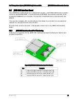
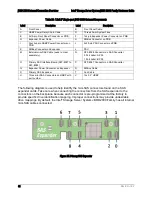
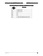
Page 47: ...ting bracket that allows the converter to be mounted and retained in a rear panel PCI mounting location No power rails power consumers or temperature sensors are on the JBOD SAS interface board 6 2 1 JBOD SAS Interface Board Port Numbering Following is a suggestion for the JBOD SAS interface board port numbering for internal and external connections Figure 33 JBOD 2000 SAS Interface Board Port Num...

Page 48: ...e board The internal mini SAS connectors should use the controller mini SAS pin out The sideband signals within the internal mini SAS connectors need to conform to the SFF 8448 specification You do not need to do the pull ups or pull downs on any sideband signals including sideband 6 and 7 when cabling externally sidebands are only for potential debug purposes on this board See the following pin o...

Page 49: ...erview Revision 1 42 39 6 3 1 JBOD2312S2SP Interconnection The Intel Storage Server System JBOD2312S2SP has a 12x3 5 single port HSBP a primary SAS expander a dual port SAS interface board a PDB a PSU and three fans in its chassis Figure 34 12x3 5 Single port JBOD 2000 Interconnection Diagram ...

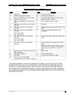
Page 50: ...nnector on SAS Converter 0 Port Label A PRI 1 Port Label B PRI O Primary SAS Interface Board SFF 8087 to SFF 8088 P SFF 8087 Connector on SAS Converter Q Expander Power Connector on Expander R SMBus Cable S Primary SAS Expander T Fan Cable U Three mini SAS Connectors on HSBP with port number V 12x 3 5 HSBP The following diagram is used to help identify the mini SAS connectors found on the SAS expa...

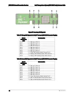
Page 51: ...S Expander in 12x3 5 Single port JBOD 2000 Connector Mapping Primary SAS Expander Label Interconnection Port 0 To Backplane Port 0 Port 1 To Backplane Port 1 Port 2 To Backplane Port 2 Port 3 N A Port 4 N A Port 5 N A Port 6 N A Port 7 To Primary SAS Interface Board Internal Port 0 Port 8 To Primary SAS Interface Board Internal Port 1 ...

Page 52: ...uide Revision 1 42 42 6 3 2 JBOD2224S2DP Interconnection The Intel Storage Server System JBOD2224S2DP has three 8x2 5 dual port HSBPs two SAS expanders three dual port SAS interface boards a PDB two PSUs and three fans in its chassis Figure 36 2U 24x2 5 Dual port JBOD2000 Interconnection Diagram ...

Page 53: ...nverter Port 0 Label A SEC Port 1 Label B SEC R Second SAS Interface Board SFF 8087 to SFF 8088 S SFF 8087 Connector on Second SAS Converter T Third SAS Interface Board SFF 8087 to SFF 8088 Note It is under the second SAS converter so it is not shown in the diagram Its external SFF 8088 connector label is Port 0 C PRI Port 1 C SEC U Expander Power Connector on Primary and Second Expander V SMBus C...

Page 54: ...Backplane Port 5A Port 6 To Third SAS Interface Board Internal Port 0 Port 7 To Primary SAS Interface Board Internal Port 0 Port 8 To Primary SAS Interface Board Internal Port 1 Table 28 Second SAS Expander in 24x2 5 Dual port JBOD 2000 Connector Mapping Second SAS Expander Label Interconnection Port 0 To Backplane Port 0B Port 1 To Backplane Port 1B Port 2 To Backplane Port 2B Port 3 To Backplane...

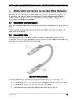
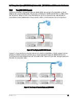
Page 55: ...controllers are referenced via our JBOD 2000 Family THOL or SCT SAS connectivity is via the external SAS connectors SFF8088 both native SAS HBAs and RAID HBAs are supported 7 2 External SAS Cable JBOD 2000 system uses SFF 8088 mini SAS receptacle so SFF 8088 mini SAS cable is needed when connecting the JBOD2000 to host or cascades to other JBOD2000 The following figure is an illustration of SFF 80...

Page 56: ... JBOD cascading is also called daisy chaining which means connecting multiple JBOD units to constitute deeper storage pool How many JBOD 2000 can be cascaded depends on the property of the SAS HBA or RAID adapter that connects to JBOD 2000 However only two layers of cascaded JBOD 2000 system have been fully validated by Intel Only cascading the same type of JBOD 2000 is recommended in order to avo...

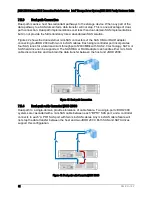
Page 57: ...RI or B PRI SAS port can be connected to the SAS adapter or cascaded with other JBOD2000 in this scenario SATA or SAS hard drive can be supported 4 4 Figure 40 Two Single port JBOD 2000 Cascade Figure 41 shows another connection scenario in which the SAS HBA or RAID adapter has two external mini SAS connectors Other group of two cascaded single port JBOD2000 can be connected to the host adapter wi...

Page 58: ... SAS cables Each single controller port incorporates four SAS lanes for a total maximum throughput of 2400MB s with SAS 2 0 technology SATA or SAS hard drive can be supported The SAS HBA or RAID adapter can handle either mini SAS cable disconnection and maintain the data transfer between the host and JBOD 2000 4 4 Figure 42 Dual path Connection 7 5 4 Dual path with Cascaded JBOD 2000 Dual path to ...

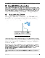
Page 59: ... In the figure the 4 notation indicates a 4 lane bundled path This dual domain SAS configuration can tolerate single port failure on the SAS controller external cable failure and failure of the expander in JBOD 2000 Figure 44 Dual domain SAS for Dual port JBOD 2000 The SAS controller in the host can be the single point of failure in the connection mode above To avoid this the second SAS controller...

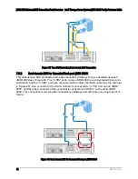
Page 60: ...dual port JBOD 2000 as in Figure 46 The C PRI ports on two JBOD 2000 are connected with one mini SAS cable and the C SEC ports are connected with another mini SAS cable see the red lines in Figure 46 One connector of the SAS controller is connected to A PRI port on one JBOD 2000 and the other connector of the controller is connected to B SEC on the other JBOD 2000 This connection mode provides red...

Page 61: ...s of the SAS controller in the first server connect to A PRI and A SEC port on JBOD 2000 with two mini SAS cables and the connectors of the SAS controller in the second server connect to B PRI and B SEC port on JBOD 2000 with other two mini SAS cables The cluster interconnect provides redundancy in the event of HBA or cable failure Dual domain SAS requires active active configurations that permit ...

Page 62: ...vision 1 42 52 4 4 4 4 4 4 Figure 48 Cascaded JBOD 2000 for a Two node Cluster Note Failover cluster usually needs special firmware and driver for SAS RAID adapter Refer to the Intel High Availability Storage User Guide at http download intel com support motherboards server sb g85745001_ha_installationguide pdf ...

Page 63: ...Family Hardware Guide Reference Documents Revision 1 42 53 Reference Documents Refer to the following documents for additional information Intel Storage Server System JBOD 2000 Family Service Guide Intel High Availability Storage User Guide ...

Reviews: