Intel
©
LB440GX 2U Rack Server Chassis TPS Rev 1.0
11
7.3 Hot-Swap Backplane Board Layout
The backplanes reside in the hot-swap drive bay of the Intel
LB440GX 2U rack server chassis. Note
this is a passive backplane, which means there is no firmware associated with it (no SAF-TE ASIC).
As a result, server management will not be able to determine the status of each drive.
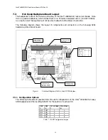
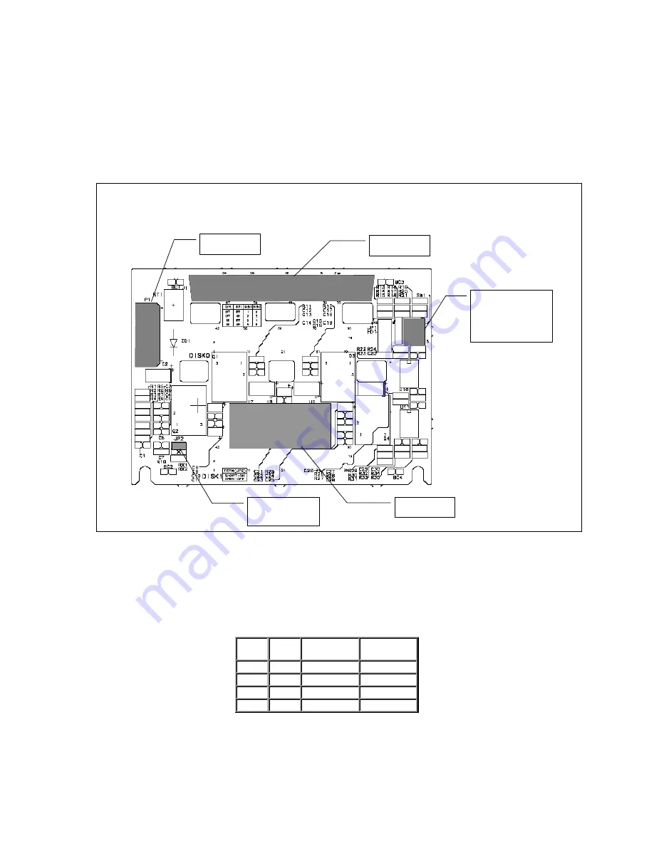
The following diagram shows the layout of components and connectors on the hot-swap SCSI
backplane printed circuit board.
68Pin SCSI CON
NECTOR
SCSI ID SW
SW2 SW1 DISK1 DISK0
OFF OFF 1 0
OFF ON 3 2
ON OFF 5 4
ON ON 9 8
SE/LVD SCSI
TERMINATOR
TERMINATOR
ENABLE : SHORT
DIABLE : OPEN
DISK POWER
CONNECTOR
Figure 6. Functional Diagram of the Hot-Swap SCSI Backplane
7.3.1 Configuration Options
The following table lists all possible SCSI ID switch configurations of the Intel
LB440GX hot-swap
SCSI backplane and the resulting SCSI ID for the position of each switch.
SW
2
SW
1
ID of Disk
1
ID of Disk
0
OFF
OFF
1
0
OFF
ON
3
2
ON
OFF
5
4
ON
ON
9
8
Table 7. HSBP Configuration Jumpers

