Intel
®
Modular Server System Service Guide
43
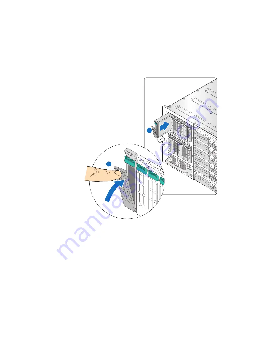
6. With the drive carrier retaining lever in the open position (see letter “A” in
Figure 30
),
carefully slide the drive carrier into the drive bay module until it is fully seated and
the retaining lever starts to engage. Press firmly to latch the retaining lever (see letter
“B” in
Figure 30
).
Figure 30. Installing 2.5-inch Drive Carrier in Drive Bay Module
Removing a 2.5-inch Hard Drive from the Storage Bay
To remove a 2.5-inch hard drive from the storage bay, follow these steps:
1. Review the safety and ESD information at the beginning of this manual and in the
appendices.
2. To avoid data corruption, ensure that the drive you intend to remove is not online and
actively providing data storage to any of the installed compute modules.
AF002426
A
B
8
9
10
11
12
13
14
1
2
3
4
5
6
7
Summary of Contents for MFSYS25V2
Page 4: ...iv Intel Modular Server System Service Guide ...
Page 14: ...xiv Intel Modular Server System Service Guide ...
Page 16: ...xvi Intel Modular Server System Service Guide ...
Page 82: ...66 Intel Modular Server System Service Guide ...
Page 137: ...Intel Modular Server System Service Guide 121 Figure 71 Storage Layout Graphical View ...
Page 144: ...128 Intel Modular Server System Service Guide Figure 79 System Information Report ...
Page 172: ...156 Intel Modular Server System Service Guide ...
Page 186: ...170 Intel Modular Server System Service Guide ...
Page 198: ...182 Intel Modular Server System Service Guide ...


