38
2.2.1
Front Panel Connectors
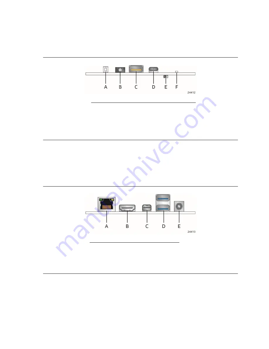
Figure 9 shows the location of the front panel connectors, controls and indicators for the board.
Figure 9. Front Panel Connectors, Controls and Indicators
Item
Description
A
Power switch and LED
B
Front panel stereo microphone/headphone jack
C
USB 3.1 Gen2 charging-capable port (amber)
D
USB 3.1 Gen 2 USB Type C
E
CIR
F
Hard drive activity LED
2.2.2
Back Panel Connectors
Figure 10 shows the location of the back panel connectors for the board.
Figure 10. Back Panel Connectors
Item
Description
A
RJ45 LAN connector
B
HDMI connector
C
Mini DP connector
D
USB 3.1 Gen2 ports
E
19V DC input jack


