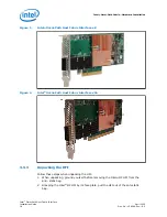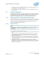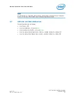
Figure 3.
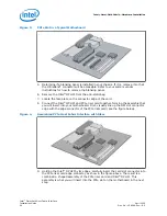
PCIe Slot in a Typical Motherboard
5. Determine if a blanking panel is installed in your chassis. If it is, remove it so that
the InfiniBand* connector will be accessible. Refer to your system vendor
instructions for how to remove the blanking panel.
6. Remove the Intel
®
OP HFI from the anti-static bag.
7. Locate the face plate on the connector edge of the card.
8. Connect the Intel
®
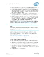
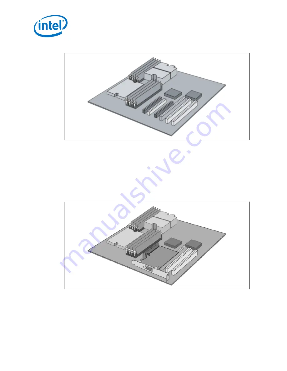
OP HFI and PCIe riser card together, forming the assembly that
you will insert into your motherboard. First, visually line up the HFI slot connector
edge with the edge connector of the PCIe riser card (see the figure below).
Figure 4.
Assembled PCIe Host Fabric Interface with Riser
9. Holding the Intel
®
OP HFI by its edges, carefully insert the card slot connector into
the PCIe riser card edge connector, as show in the figure above. The result is a
combined L- shaped assembly of the PCIe riser card and Intel
®
OP HFI. This
assembly is what you will insert into the PCIe slot on the motherboard in the next
step.
Intel
®
Omni-Path Fabric—Hardware Installation
Intel
®
Omni-Path Host Fabric Interface
Installation Guide
April 2020
20
Doc. No.: H76466, Rev.: 8.0


