


9
General Installation Process
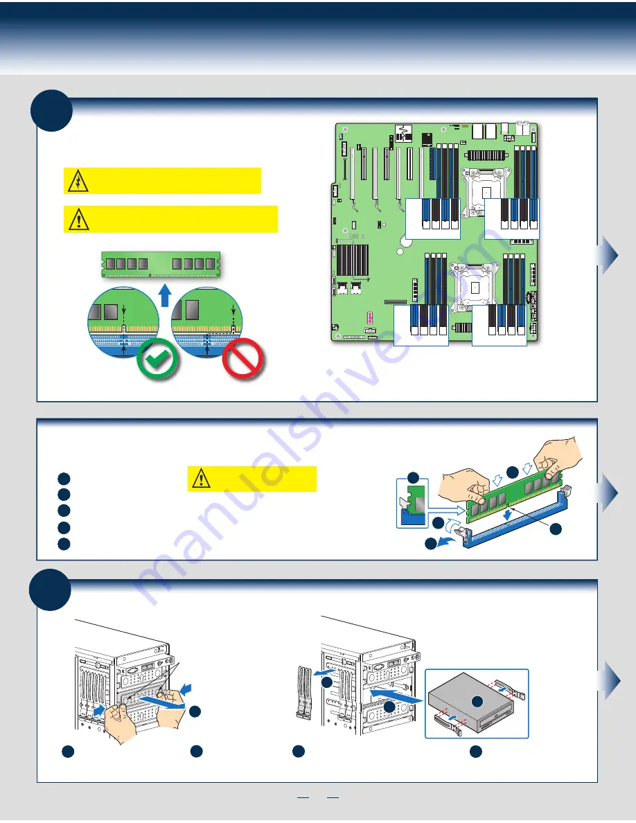
Install DIMM Memory Modules
... Continued
To Install DIMMs:
Open both DIMM socket levers.
C
A
D
E
Note location of alignment notch.
B
CAUTION: Avoid touching contacts
when handling or installing DIMMs.
A
C
D
B
E
IMPORTANT! Visually check that each latch is fully closed and correctly engaged with each DIMM edge slot.
Push down firmly on the DIMM until it snaps into place and both levers close.
Insert DIMM making sure the connector edge of the DIMM aligns correctly with the slot.
7
Install Tool-less CD-ROM or DVD-ROM Drive
C
Attach slides to the DVD or CD-ROM drive
by pressing the slides firmly into the side
dimples on the DVD or CD-ROM drive.
B
Get the slides from the
chassis side.
D
Insert the drive/slide assembly
into the device bay until the
slides lock into place.
A
Press the release latch and use
the finger holes to Pull out the
EMI shield.
Finger Holes
A
D
B
C
6
Install DIMM Memory Modules
DDR3 DIMM Memory Ide
ntification:
DIMM
notch and
socket
bump must
align as
shown.
Other
Memory
DDR3
This server board supports up to 16 DDR3 800/1066/1333/1600 ECC
UDIMM/RDIMM/LRDIMM.
CAUTION:
Observe normal ESD (ElectroStatic Discharge) procedures
to avoid possible damage to system components.
Memory sizing and configuration is supported only for qualified DIMMs approved by Intel. For a list of
supported memory, see the tested memory list at
http://serverconfigurator.intel.com/default.aspx
Memory Type:
Minimum of one 1 GB, DDR3 800/1066/1333/1600 MHz ECC UDIMM/RDIMM/LRDIMM.
C1
DIMM
C2 D1 D2
B2
DIMM
B1 A2 A1
E1
DIMM
E2 F1 F2
H2
DIMM
H1 G2 G1
Summary of Contents for P4000CR
Page 11: ...G49309 003 ...


