


10
General Installation Process
H
G
A
B
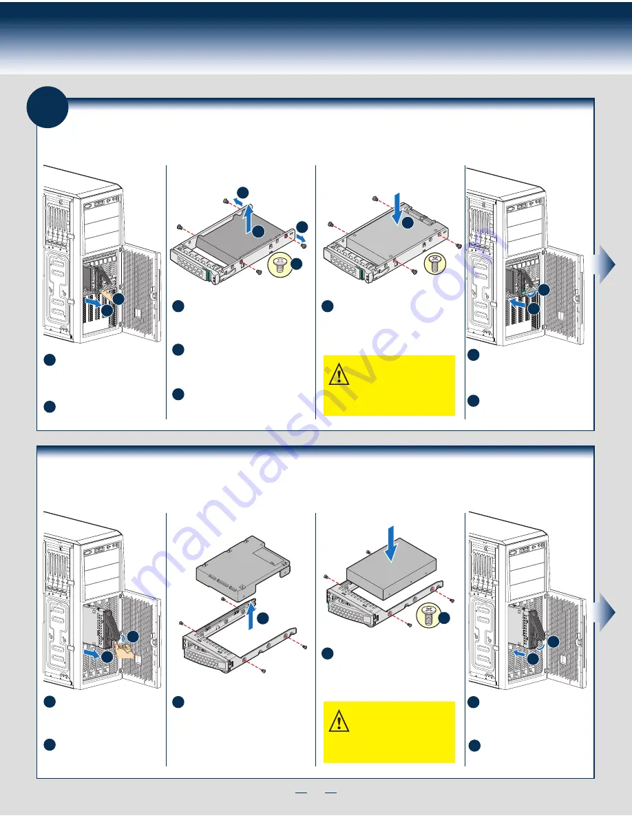
Install Hard Drive
2.5" Hot-Swap Hard Drive Carrier (For system with 2.5" hot-swap hard drive bay only)
A
Open the Hot-swap door and
remove the drive carrier by
pressing the
green
button and
opening the lever.
Slide the carrier out.
B
D
D
E
C
2.5" HDD
F
Remove the four screws securing the
plastic retention device to the 2.5"
HDD carrier.
Disengage the plastic retention device
from the HDD carrier slides by
pulling the slides.
Remove the plastic retention device
from the 2.5" HDD carrier.
C
D
E
Install the hard disk drive using the
four screws as shown. Make sure the
connector end of the drive matches
the backplane connector.
F
CAUTION: If you don’t install all
drives, empty drive bays must
be occupied by carriers with
plastic drive blank provided to maintain
proper system cooling.
With the lever open, insert the
hard disk drive assembly into the
cage opening and push until the
locking lever engaged.
Push in the lever to lock it into
place, then close the door.
G
H
8
E
F
B
A
Install Hard Drive ...
Continued
3.5" Hot-Swap Hard Drive Carrier (For system with 3.5" hot-swap hard drive bay only)
A
Open the Hot-swap door and
remove the drive carrier by
pressing the
green
button and
opening the lever.
Slide the carrier out.
B
Remove the four screws securing the
HDD interface bracket and remove the
HDD interface bracket.
C
Install the hard disk drive using the
same four screws as shown. Make
sure the connector end of the drive
matches the backplane connector.
D
CAUTION: If you don’t install all
drives, empty drive bays must
be occupied by carriers with
plastic drive blank provided to maintain
proper system cooling.
With the lever open, insert the
hard disk drive assembly into the
cage opening and push until the
locking lever engaged.
Push in the lever to lock it into
place, then close the door.
E
F
TOP
BREAK OFF T
AB
BEFORE MOUTING
2.5´´ HARD DRIVE
C
3.5´´ HDD
D
Summary of Contents for P4000CR
Page 11: ...G49309 003 ...


