background image

15

Reference

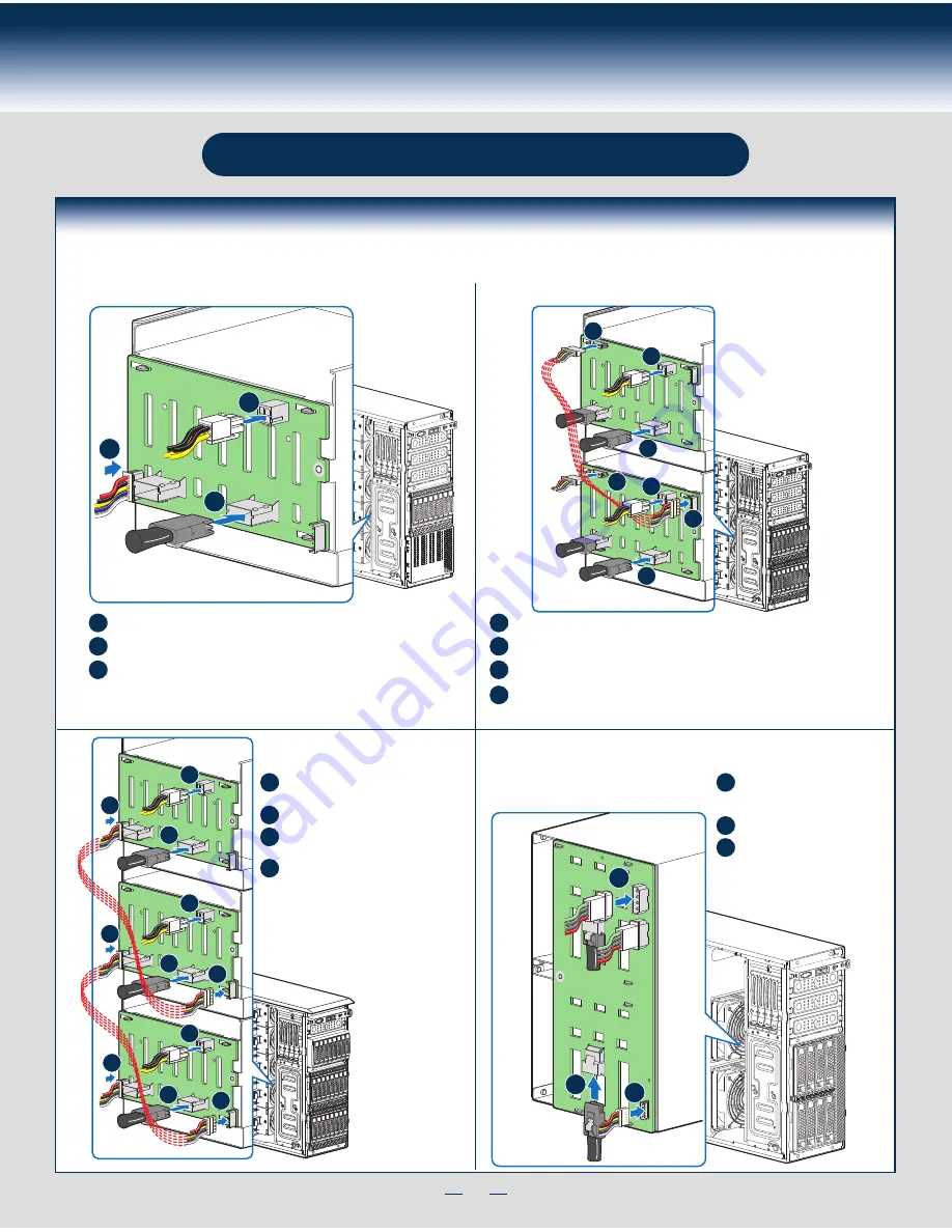
HDD Cage Cable Connection

A

C

C

D

D

B

B

Connect the I

2

C cable to I

2

C_IN connector on bottom 8x2.5" backplane.

A

Connect Mini SAS data cables.

B

Connect power cables* (1 x 4 to 2 x 2 Power adapter cable is needed).

C

Connect the I

2

C cable to I

2

C_IN connector on bottom 8x2.5" backplane.

A

Connect Mini SAS data cables.

B

Connect power cables* (1 x 4 to 2 x 2 Power adapter cable is needed).

C

Connect I

2

C_OUT connector on bottom 8x2.5" backplane to I

2

C_IN connector

on top 8x2.5" backplane for backplane cascade.

D

Connect the I

2

C cable to I

2

C_IN connector

on bottom 8x2.5" backplane.

A

Connect Mini SAS data cables.

B

Connect power cables* (1 x 4 to 2 x 2

Power adapter cable is needed).

C

Connect the I

2

C cable to I

2

C_IN

connector on bottom 8x2.5"

backplane.

A

Connect Mini SAS data cables.
Connect the two power cables.

B

C

Connect I

2

C_OUT connector on bottom

8x2.5" backplane to I

2

C_IN connector

on top 8x2.5" backplane for backplane

cascade.

D

Note: Refer to the documentation that came with your server board and/or RAID controller card for instructions on connecting backplane cables to your server board or 

RAID controller card.

8 x 2.5" HDD Cage

8 x 3.5" HDD Cage

16 x 2.5" HDD Cage

24 x 2.5" HDD Cage

A

C

B

A

C

D

B

C

D

B

C

D

B

D

A

B

C

Summary of Contents for P4000CR

Page 1: ...cover outward to remove it 2 Server Board A A B 1 Preparing the System Observe normal ESD Electrostatic Discharge procedures Place your Intel Server System on a flat anti static surface to perform the following integration procedures Observe ESD procedures before reaching inside to make server board connections or install components 3 Remove the Air Duct A Remove the air duct A 4 Install the Proce...

Page 2: ...ke the processor out of the box and remove the protective shipping cover CAUTION When unpacking a processor hold by the edges only to avoid touching the gold contact pins Save the protective cover A CAUTION The underside of the processor has components that may damage the socket pins if installed improperly Processor must align correctly with the socket opening before installation DO NOT DROP proc...

Page 3: ...slides from the chassis side D Insert the drive slide assembly into the device bay until the slides lock into place A Press the release latch and use the finger holes to Pull out the EMI shield Finger Holes A D B C 6 Install DIMM Memory Modules DDR3 DIMM Memory Identification DIMM notch and socket bump must align as shown Other Memory DDR3 This server board supports up to 16 DDR3 800 1066 1333 1600...

Page 4: ...rt the hard disk drive assembly into the cage opening and push until the locking lever engaged Push in the lever to lock it into place then close the door G H 8 E F B A Install Hard Drive Continued 3 5 Hot Swap Hard Drive Carrier For system with 3 5 hot swap hard drive bay only A Open the Hot swap door and remove the drive carrier by pressing the green button and opening the lever Slide the carrie...

Page 5: ...dd in board retention device Rotate the PCI card retainer until the PCI card retainer is secured by the chassis Make sure the PCI card is secured into the slot under the PCI Card Retainer Server Board F Server Board G 9 Install PCI Card Assembly A Remove the PCI slot shield by pushing the shield out from inside the chassis B Rotate the PCI retainer all the way to open C Install the optional PCI e ...

Page 6: ...rver board Server Board RMM4 NIC Connector Server Board C E Chassis Back Opening Filler D B CAUTION Carefully remove the knock out with screwdriver directly removing it with finger has potential risk CAUTION Care should be used when attaching or removing this cable Mishandling the cable could cause damage 12 Install Alternate Serial Port optional A Remove the alternate serial port knockout by pres...

Page 7: ...in through the rubber foot B A B Note This step applies to your chassis if configured as a pedestal system If you plan to configure your chassis as a rack mount system disregard this step Note Repeat above steps until all four feet are installed 13 Install Intel RAID Smart Battery optional Align the tabs on the plastic battery holder with the mounting holes in the chassis and slide the plastic bat...

Page 8: ...Install Software BIOS Drivers and Operating System Install A Confirm BIOS Version Look on the Server System Management screen in the BIOS Setup Utility to determine the installed BIOS version Compare this to the versions at http www intel com support If new versions are available update the BIOS on your server See the User Guide on the Intel Server Deployment and Management DVD for update instructi...

Page 9: ... Connect the I2 C cable to I2 C_IN connector on bottom 8x2 5 backplane A Connect Mini SAS data cables B Connect power cables 1 x 4 to 2 x 2 Power adapter cable is needed C Connect the I2 C cable to I2 C_IN connector on bottom 8x2 5 backplane A Connect Mini SAS data cables Connect the two power cables B C Connect I2 C_OUT connector on bottom 8x2 5 backplane to I2 C_IN connector on top 8x2 5 backpla...

Page 10: ...able H System FAN 1 I System FAN 2 Description A CPU1 CPU2 Power Cable B Server Board Main Power Cable C Backplane Power Cable D ODD Power Cable E Front Panel Cable USB Cable F ODD Data Cable Connect To White SATA 6G Connectors On Server Board G MiniSAS with SGPIO Cable H PMBus Cable I HSBP_I2 C Cable From Server Board To First Backplane J HSBP_I2 C Cable From First Backplane To Second Backplane w...

Page 11: ...G49309 003 ...

Reviews: