8-9
DATA INTEGRITY
8.3.5.
BINIT# Signal and Protocol
BINIT# is asserted when any Pentium Pro processor agent detects a fatal error and BINIT# driv-
er is enabled. Sampling of BINIT#, if enabled, resets all bus state, clearing a path for an excep-
tion handler (disabling of BINIT# driving/sampling is provided for power on diagnostics only).
This typically causes undefined termination of all pending transactions. Therefore, it cannot be
used to fully recover from the original error state. However, once the bus pipeline is reset for all
Pentium Pro processor bus agents, it is possible to run an exception handler to log the error. If
CR4.MCE is set, all Pentium Pro processors on the bus enter the MCE handler. If not set, IERR#
to BERR# reporting should be enabled so bus error reporting can generate an interrupt (NMI)
or soft reset (INIT#). The programmer-visible register state can be read by the exception handler
to attempt graceful error logging.
On observation of active BINIT#, all Pentium Pro processor bus agents must do the following:
•
Deassert all signals on the bus.
•
Reset the arbitration IDs to the value used at power-on reset.
•
Reset the transaction queues included the In-order Queue.
•
Begin a new arbitration sequence for the request bus and continue.
•
Return programmer-visible register state and cache state to their previous values.
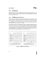
The BINIT# protocol takes into account multiple bus agents trying to assert BINIT# at the same
time, as shown in Figure 8-2. Once BINIT# is asserted by one bus agent, all agents ensure that
it is asserted for exactly three clocks. An agent intending to assert BINIT# observes BINIT# to
ensure that it is inactive. If the agent samples BINIT# inactive in the clock it first drives BINIT#,
it retains BINIT# active for exactly three clocks. If the agent samples BINIT# active in the clock
it first drives BINIT#, (due to another bus agent asserting BINIT# one clock prior to its assertion
of BINIT#) it retains BINIT# active for exactly two clocks.
Summary of Contents for Pentium Pro Family
Page 17: ...1 Component Introduction ...
Page 26: ...2 Pentium Pro Processor Architecture Overview ...
Page 27: ......
Page 36: ...3 Bus Overview ...
Page 62: ...4 Bus Protocol ...
Page 105: ...5 Bus Transactions and Operations ...
Page 126: ...6 Range Registers ...
Page 131: ...7 Cache Protocol ...
Page 135: ...8 Data Integrity ...
Page 148: ...9 Configuration ...
Page 161: ...10 Pentium Pro Processor Test Access Port TAP ...
Page 172: ...11 Electrical Specifications ...
Page 201: ...12 GTL Interface Specification ...
Page 229: ...13 3 3V Tolerant Signal Quality Specifications ...
Page 233: ...14 Thermal Specifications ...
Page 239: ...15 Mechanical Specifications ...
Page 241: ...15 2 MECHANICAL SPECIFICATIONS s Figure 15 1 Package Dimensions Bottom View ...
Page 252: ...16 Tools ...
Page 260: ...16 8 TOOLS Figure 16 4 Generic MP System Layout for Debug Port Connection ...
Page 264: ...17 OverDrive Processor Socket Specification ...
Page 290: ...A Signals Reference ...
Page 320: ...Index ...
Page 328: ......


