11-4
ELECTRICAL SPECIFICATIONS
Adequate decoupling capacitance should be placed near the power pins of the Pentium Pro pro-
cessor. Low inductance capacitors such as the 1206 package surface mount capacitors are rec-
ommended for the best high frequency electrical performance. Forty (40) 1
µ
F 1206-style
capacitors with a
±
22% tolerance make a good starting point for simulations as this is our rec-
ommended decoupling when using a standard Pentium Pro processor Voltage Regulator Mod-
ule. Inductance should be reduced by connecting capacitors directly to the VccP and Vss planes
with minimal trace length between the component pads and vias to the plane. Be sure to include
the effects of board inductance within the simulation. Also, when choosing the capacitors to use,
bear in mind the operating temperatures they will see and the tolerance that they are rated at.
Type Y5S or better are recommended (
±22
% tolerance over the temperature range -30
°
C to
+85
°
C).
Bulk capacitance with a low Effective Series Resistance (ESR) should also be placed near the
Pentium Pro processor in order to handle changes in average current between the low power and
normal operating states. About 4000
µ
F of capacitance with an ESR of 5m
Ω
makes a good start-
ing point for simulations, although more capacitance may be needed to bring the ESR down to
this level due to the current technology in the industry. The standard Pentium Pro processor Volt-
age Regulator Modules already contain this bulk capacitance. Be sure to determine what is avail-
able on the market before choosing parameters for the models. Also, include power supply
response time and cable inductance in a full simulation.
See AP-523 Pentium
®
Pro Processor Power Distribution Guidelines Application Note (Order
Number 242764) for power modeling for the Pentium Pro processor.
11.4.1.
VccS Decoupling
Decoupling of ten (10) 1
µ
F ceramic capacitors (type Y5S or better) and a minimum of five 22
µ
F
tantalum capacitors is recommended for the VccS pins. This is to handle the transients that may
occur in future devices. These are not required for the processors described herein.
11.4.2.
GTL+ Decoupling
Although the Pentium Pro processor GTL+ bus receives power external to the Pentium Pro pro-
cessor, it should be noted that this power supply will also require the same diligent decoupling
methodologies as the processor. Notice that the existence of external power entering through the
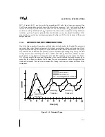
I/O buffers causes Vss current to be higher than the Vcc current as evidenced in Figure 11-2.
11.4.3.
Phase Lock Loop (PLL) Decoupling
Isolated analog decoupling is required for the internal PLL. This should be equivalent to 0.1µF
of ceramic capacitance. The capacitor should be type Y5R or better and should be across the
PLL1 and PLL2 pins of the Pentium Pro processor. (“Y5R” implies
±
15% tolerance over the
temperature range -30
°
C to +85
°
C.)
Summary of Contents for Pentium Pro Family
Page 17: ...1 Component Introduction ...
Page 26: ...2 Pentium Pro Processor Architecture Overview ...
Page 27: ......
Page 36: ...3 Bus Overview ...
Page 62: ...4 Bus Protocol ...
Page 105: ...5 Bus Transactions and Operations ...
Page 126: ...6 Range Registers ...
Page 131: ...7 Cache Protocol ...
Page 135: ...8 Data Integrity ...
Page 148: ...9 Configuration ...
Page 161: ...10 Pentium Pro Processor Test Access Port TAP ...
Page 172: ...11 Electrical Specifications ...
Page 201: ...12 GTL Interface Specification ...
Page 229: ...13 3 3V Tolerant Signal Quality Specifications ...
Page 233: ...14 Thermal Specifications ...
Page 239: ...15 Mechanical Specifications ...
Page 241: ...15 2 MECHANICAL SPECIFICATIONS s Figure 15 1 Package Dimensions Bottom View ...
Page 252: ...16 Tools ...
Page 260: ...16 8 TOOLS Figure 16 4 Generic MP System Layout for Debug Port Connection ...
Page 264: ...17 OverDrive Processor Socket Specification ...
Page 290: ...A Signals Reference ...
Page 320: ...Index ...
Page 328: ......


