11-19
ELECTRICAL SPECIFICATIONS
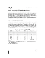
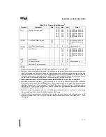
NOTE:
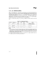
1. Only those indicated here are tested during the manufacturing test process.
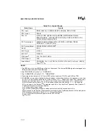
NOTES:
1. Valid delay timings for these signals are specified into an idealized 25
Ω
resistor to 1.5V with VREF at
1.0V. Minimum values guaranteed by design. See Figure 12-11 for the actual test configuration.
2. GTL+ timing specifications for 166MHz and higher components are PRELIMINARY. Consult your
local FAE.
3. A minimum of 3 clocks must be guaranteed between 2 active-to-inactive transitions of TRDY#.
4. RESET# can be asserted (active) asynchronously, but must be deasserted synchronously.
5. Specification takes into account a 0.3V/ns edge rate and the allowable VREF variation.
Guaranteed by design.
6. After Vcc, VTT, VREF, BCLK and the clock ratio become stable.
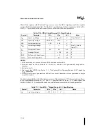
Table 11-10. Supported Clock Ratios
1
PART:
2X
5/2X
3X
7/2X
4X
150MHz
X
X
X
166MHz
X
X
180MHz
X
X
200MHz
X
X
X
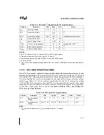
Table 11-11. GTL+ Signal Groups A.C. Specifications
RL = 25
Ω
terminated to 1.5V, VREF = 1.0V
T#
Parameter
Min
Max
Unit
Figure
Notes
T7A: GTL+ Output Valid Delay
H
→
L
0.55
0.80
4.4
4.4
ns
ns
11-8
@ 150MHz, 256K L2
All other components
1, 2
T7B: GTL+ Output Valid Delay
L
→
H
0.55
0.80
3.9
3.9
ns
ns
11-8
@ 150MHz, 256K L2
All other components
1
T8:
GTL+ Input Setup Time
2.2
ns
11-9
3, 4, 5
T9:
GTL+ Input Hold Time
0.45
0.70
ns
ns
11-9
@ 150MHz, 256K L2
All other components
5
T10: RESET# Pulse Width
1
ms
11-12
11-13
6
Summary of Contents for Pentium Pro Family
Page 17: ...1 Component Introduction ...
Page 26: ...2 Pentium Pro Processor Architecture Overview ...
Page 27: ......
Page 36: ...3 Bus Overview ...
Page 62: ...4 Bus Protocol ...
Page 105: ...5 Bus Transactions and Operations ...
Page 126: ...6 Range Registers ...
Page 131: ...7 Cache Protocol ...
Page 135: ...8 Data Integrity ...
Page 148: ...9 Configuration ...
Page 161: ...10 Pentium Pro Processor Test Access Port TAP ...
Page 172: ...11 Electrical Specifications ...
Page 201: ...12 GTL Interface Specification ...
Page 229: ...13 3 3V Tolerant Signal Quality Specifications ...
Page 233: ...14 Thermal Specifications ...
Page 239: ...15 Mechanical Specifications ...
Page 241: ...15 2 MECHANICAL SPECIFICATIONS s Figure 15 1 Package Dimensions Bottom View ...
Page 252: ...16 Tools ...
Page 260: ...16 8 TOOLS Figure 16 4 Generic MP System Layout for Debug Port Connection ...
Page 264: ...17 OverDrive Processor Socket Specification ...
Page 290: ...A Signals Reference ...
Page 320: ...Index ...
Page 328: ......


