16-5
TOOLS
16.2.4.7.
SIGNAL NOTE 7: TRST#
If the TRST# signal is connected to the 82454GX, it should be pulled down through a 470 ohm
resistor.
16.2.4.8.
SIGNAL NOTE 8: TCK
*WARNING: A significant number of target systems have signal integrity issues with the TCK
signal. TCK is a high speed signal and must be routed accordingly; make sure to observe power
and ground plane integrity for this signal. Follow the guidelines below and assure the quality of
the signal when beginning use of an ITP to debug your target.
Due to the number of loads on the TCK signal, special care should be taken when routing it.
Poor routing can lead to multiple clocking of some agents on the debug chain, usually on the
falling edge of TCK. This causes information to be lost through the chain and can result in bad
commands being issued to some agents on the bus. There are two known good routing
schemes for the TCK signal: daisy chain and star. Systems using other TCK routing schemes,
particularly those with “T” or “Y” configurations where the trace from the source to the “T” is
long, invite signal integrity problems.
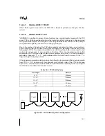
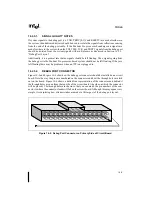
If the signal is more easily routed as a daisy chain then it is recommended that a pull-up resistor
from TCK to 3.3V be placed at the physically most distant node of the TCK route (see
Figure 16-2). This resistor should be between 62 and 150 Ohms, depending on the run length of
the TCK trace. Use Table 16-2 to select a value:
Table 16-2. TCK Pull-Up Value
Run Length
Resistor
0 - 12"
150 ohms
12 - 15"
120 ohms
15 - 18"
100 ohms
18 - 21"
82 ohms
> 21"
62 ohms
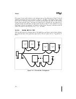
Figure 16-2. TCK with Daisy Chain Configuration
Pentium®
Pro
Pentium
Pro
Pentium
Pro
Summary of Contents for Pentium Pro Family
Page 17: ...1 Component Introduction ...
Page 26: ...2 Pentium Pro Processor Architecture Overview ...
Page 27: ......
Page 36: ...3 Bus Overview ...
Page 62: ...4 Bus Protocol ...
Page 105: ...5 Bus Transactions and Operations ...
Page 126: ...6 Range Registers ...
Page 131: ...7 Cache Protocol ...
Page 135: ...8 Data Integrity ...
Page 148: ...9 Configuration ...
Page 161: ...10 Pentium Pro Processor Test Access Port TAP ...
Page 172: ...11 Electrical Specifications ...
Page 201: ...12 GTL Interface Specification ...
Page 229: ...13 3 3V Tolerant Signal Quality Specifications ...
Page 233: ...14 Thermal Specifications ...
Page 239: ...15 Mechanical Specifications ...
Page 241: ...15 2 MECHANICAL SPECIFICATIONS s Figure 15 1 Package Dimensions Bottom View ...
Page 252: ...16 Tools ...
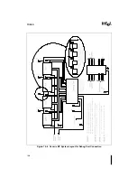
Page 260: ...16 8 TOOLS Figure 16 4 Generic MP System Layout for Debug Port Connection ...
Page 264: ...17 OverDrive Processor Socket Specification ...
Page 290: ...A Signals Reference ...
Page 320: ...Index ...
Page 328: ......


